I've tried creating an automatic fundamental nulling circuit for LtSpice:
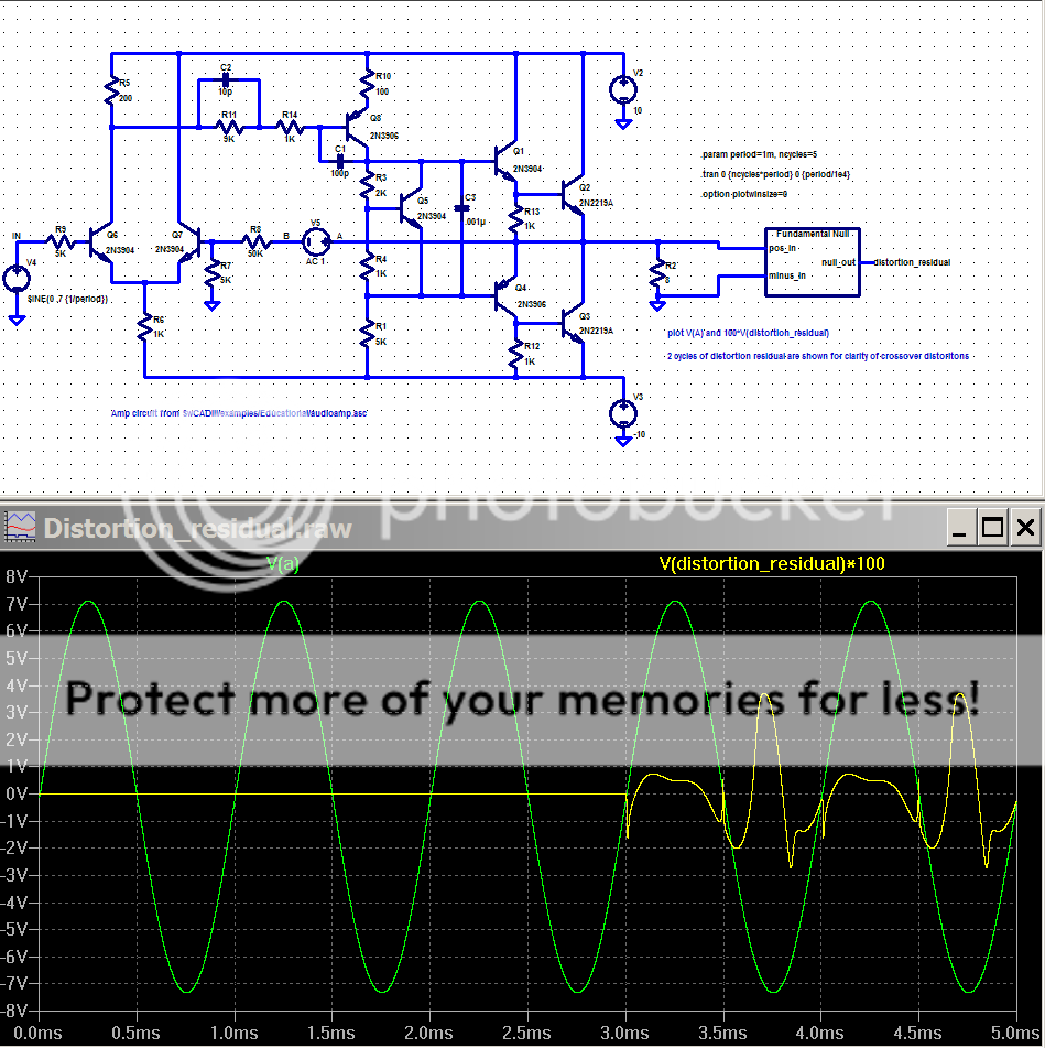
comments from the Fundamental_Null.asc (included in zip):
Fundamental_Null Distortion Residual viewing tool
requires Fundamental_Null.asy ( may be put in \lib\sym\Misc )
requires Fundamental_Null.asc ( same path as .asc calling the tool )
at top level declare:
.param period=nn, ncycles=mm
.tran 0 {ncycles*period} 0 {period/1e4}
.option plotwinsize=0
use stimulus Vsource sin(0 xx {1/period})
Automatically calculates amplitude and phase of fundamental of length {period}
of signal connected to pos_in, minus_in
using the 3rd from last cycle of {ncycles}
Subtracts fundamental and average DC component found in 3rd from last {ncycles}
from last 2 cycles for display at null_out
Attachments
Hi,
I think SPICE simulations it's a good thing. 🙂 My favorite it's Orcad PSpice.
The most frequent problem that I encounter is, of course, that I don't find all the components that I need.
For example : I started an amplifier schematics and I don't find 2SD669/2SB649 transistors.
It is posible that WE ( the users of this program ) can create the components that we need from datasheet ? Because if we don't it's useless.
If anyone knows how to do that pleaseeeee let me know.
Thanks
to Andy for providing 2SK1530 model here - it did allow me to get a nice result in my output stage simulation:
http://www.diyaudio.com/forums/showthread.php?s=&postid=1335401#post1335401
Cheers
Alex
to Andy for providing 2SK1530 model here - it did allow me to get a nice result in my output stage simulation:
http://www.diyaudio.com/forums/showthread.php?s=&postid=1335401#post1335401
Cheers
Alex
I'm working to make the approach of andy_c more usable.
However I'm encountering some problems ...
The main problem is that the function to be minimized has so many fake minima that it's realy hard, once reached a solution, to say that is the best solution or, at least, a good solution.
The methodology I have depicted seems to give some good and stable solution. By "good" I mean a solution that fits well the specifications sheet data, by "stable" I mean a solution that stays the same even if the initial, guess, parameters are slightly changed.
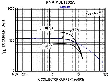
Unfortunately, for the MJE1302 I get (for the static parameters) values
+IS=2.683E-9
+BF=286.774
+NF=1.323
+VAF=119.762
+IKF=10.525
+ISE=9.803E-11
+NE=1.475
+BR=0.5
+NR=1.09511
+VAR=58.672
+IKR=0.3
+ISC=1E-13
+RB=2.237
different from the ones proposed by andy_c.
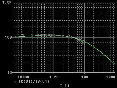
In LTSpice I see some sort of discontinuity at 80A, even if if this discontinuity is not there in PSPICE:
So, my question is: at what condition a solution is a good solution ? is there any "sanity check" to apply ?
Thanks
However I'm encountering some problems ...
The main problem is that the function to be minimized has so many fake minima that it's realy hard, once reached a solution, to say that is the best solution or, at least, a good solution.
The methodology I have depicted seems to give some good and stable solution. By "good" I mean a solution that fits well the specifications sheet data, by "stable" I mean a solution that stays the same even if the initial, guess, parameters are slightly changed.
Unfortunately, for the MJE1302 I get (for the static parameters) values
+IS=2.683E-9
+BF=286.774
+NF=1.323
+VAF=119.762
+IKF=10.525
+ISE=9.803E-11
+NE=1.475
+BR=0.5
+NR=1.09511
+VAR=58.672
+IKR=0.3
+ISC=1E-13
+RB=2.237
different from the ones proposed by andy_c.
In LTSpice I see some sort of discontinuity at 80A, even if if this discontinuity is not there in PSPICE:
So, my question is: at what condition a solution is a good solution ? is there any "sanity check" to apply ?
Thanks
teodorom said:I'm working to make the approach of andy_c more usable.
However I'm encountering some problems ...
The main problem is that the function to be minimized has so many fake minima that it's realy hard, once reached a solution, to say that is the best solution or, at least, a good solution.
The methodology I have depicted seems to give some good and stable solution. By "good" I mean a solution that fits well the specifications sheet data, by "stable" I mean a solution that stays the same even if the initial, guess, parameters are slightly changed.
Unfortunately, for the MJE1302 I get (for the static parameters) values
+IS=2.683E-9
+BF=286.774
+NF=1.323
+VAF=119.762
+IKF=10.525
+ISE=9.803E-11
+NE=1.475
+BR=0.5
+NR=1.09511
+VAR=58.672
+IKR=0.3
+ISC=1E-13
+RB=2.237
different from the ones proposed by andy_c.
In LTSpice I see some sort of discontinuity at 80A, even if if this discontinuity is not there in PSPICE:
So, my question is: at what condition a solution is a good solution ? is there any "sanity check" to apply ?
Thanks
I've been casually looking at models due to the fact that so many seem to have issues from OnSemi. This document seems to be helpful have you seen it before?
http://www.intusoft.com/lit/WkwModels.pdf
Pete B.
I've seen some medium power transistors (OnSemi MJE243/253) with 100 to 400 ohm values for RB. From that document, page 32:
"Beware of device models that contain large (> 10 Ohms) values for RB without the specification of IRB and RBM. Their small signal behavior may be correct, but they will be incorrectly biased.
Pete B.
"Beware of device models that contain large (> 10 Ohms) values for RB without the specification of IRB and RBM. Their small signal behavior may be correct, but they will be incorrectly biased.
Pete B.
Thank you. Me I have used also
http://eesof.tm.agilent.com/docs/iccap2002/MDLGBOOK/7DEVICE_MODELING/3TRANSISTORS/1GummelPoon/GP_DOCU.pdf
http://eesof.tm.agilent.com/docs/iccap2002/MDLGBOOK/7DEVICE_MODELING/3TRANSISTORS/1GummelPoon/GP_DOCU.pdf
LTspice for dummies
I have finally decided to give up on Multisim and have installed LTspice. I’ve got the schematic entry, waveform viewer sussed and have worked out how to add components into the model list.
I have started with a simple emitter follower using Andy’s RET model.
Now that’s all fine and dandy, but how the hell do I analyse THD then? I can’t find no pretty THD box like in Multisim. The help files that come with LTspice are pretty hopeless here.
Cheers,
Glen
Attachments

Re: LTspice for dummies
Hi Glen,
Why did you give up on Multisim?
G.Kleinschmidt said:I have finally decided to give up on Multisim
Hi Glen,
Why did you give up on Multisim?
Re: Re: LTspice for dummies
It only goes to down to 0.001% THD and graphing/plotting capabilities are hopeless.
MJL21193 said:
Hi Glen,
Why did you give up on Multisim?
It only goes to down to 0.001% THD and graphing/plotting capabilities are hopeless.
Re: LTspice for dummies
Does this help: http://www.diyaudio.com/forums/showthread.php?postid=1309200#post1309200
Or: http://www.diyaudio.com/forums/showthread.php?postid=1288439#post1288439
G.Kleinschmidt said:I have finally decided to give up on Multisim and have installed LTspice. I’ve got the schematic entry, waveform viewer sussed and have worked out how to add components into the model list.
I have started with a simple emitter follower using Andy’s RET model.
Now that’s all fine and dandy, but how the hell do I analyse THD then? I can’t find no pretty THD box like in Multisim. The help files that come with LTspice are pretty hopeless here.
Cheers,
Glen
Does this help: http://www.diyaudio.com/forums/showthread.php?postid=1309200#post1309200
Or: http://www.diyaudio.com/forums/showthread.php?postid=1288439#post1288439
Re: Re: Re: LTspice for dummies
Do you have the full version with an extensive model library?
Do they validate their models as some of the other better vendors do?
G.Kleinschmidt said:
It only goes to down to 0.001% THD and graphing/plotting capabilities are hopeless.
Do you have the full version with an extensive model library?
Do they validate their models as some of the other better vendors do?
Any opinions on this from page 37:
http://www.intusoft.com/lit/WkwModels.pdf
"The turn-off behavior of the power BJT can be approximated by
paralleling BJTs and using a base resistor to connect the bases
of the transistors. The topology shown in the subcircuit below
will produce the turn-off tail associated with quasi-saturation.
The value of RB and IKF will tend to control the turn-off tail.
.SUBCKT NPWR 1 2 3
Q1 1 2 3 QPWR AREA=.67
Q2 1 4 3 QPWR AREA=.33
RB 2 4 {RB}"
Some here have complained that SPICE cannot model temperature changes as a state variable during simulation. This is true for most SPICE simulators but it is a feature of Intusoft's SPICE. I'm not associated with them in any way. I simply chose their product years ago, and read their newsletter for many years. From page 21-2:
http://www.intusoft.com/nlpdf/nl21.pdf
"In the July and October 1988 newsletters (newsletters 10 and 11),
Intusoft introduced thermal models for diodes, transistors, ther-
mistors, and a tungsten lamp. The models are unique because
they are able to use temperature as a state variable, a feature not
inherently available in any SPICE program, where temperature is
normally a constant throughout the simulation. This modeling
feature allows an analysis to proceed with temperature playing a
controlling force in the simulation process as opposed to a simple
constant."
Re: Re: Re: Re: LTspice for dummies
Not yet.
1) No
2) Dunno
PB2 said:
Not yet.
PB2 said:
Do you have the full version with an extensive model library?
Do they validate their models as some of the other better vendors do?
1) No
2) Dunno
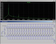
In LtSpice:
I find the Blackman window most useful in the fft, I don't find the "exact 2**n time step" calc to be useful - spice will take more smaller steps if necessary so it ends up interpolating from the (unevenly sampled) transient analysis data points to get the even time step data for the fft anyway - but the min time step should be set to force more transient steps than the fft bins you plan to use
an integer number of fundamental cycles in the analysis time is however a necessity > 4x is required with Blackman to fully separate the peaks
but to literally get a THD number you should use the .four command:
".FOUR -- Compute a Fourier Component after a .TRAN Analysis
Syntax: .four <frequency> [Nharmonics] [Nperiods] <data trace1> [<data trace2> ...]
Example: .four 1kHz V(out)
This command is performed after a transient analysis. It's supplied in order to be compatible with legacy SPICE simulators. The output from this command is printed in the .log file. Use the menu item "View=>Spice Error Log" to see the output. For most purposes, the FFT capability built into the waveform viewer is more useful.
If the integer Nharmonics is present, then the analysis includes that number of harmonics. The number of harmonics defaults to 9 if not specified.
The Fourier analysis is performed over the period from the final time, Tend, to one period before Tend unless an integer Nperiods is given after Nharmonics. If Nperiods is given as -1, the Fourier analysis is performed over the entire simulation data range.
"
- Home
- Design & Build
- Software Tools
- Spice simulation