Joseph K said:
So, I would conclude here - for me this all means, that we have one problem less - though Carlos's snubber is not effective at this point, with these kind of transformers & diodes it is also not needed, to rigorously apply the classic snubbing method.
Ciao, George
Joseph,
I am am having difficulty parsing the sentence. Would you be so kind as to restate your conclusion?
Hi, moving_electron!
The best thing that I can do for illustrating this is to copy here a pic from that article, by Francesco Callegari. I do not know if it's possible. I would put that here now, and in case of any problems, moderators, please, could you remove it?
The transformer should recharge our reservoir capacitor. The audio circuit drains this capacitor, the transformer recharges. But it recharges in the form of short current pulses, not continously. When not recharging, it is disconnected from the rest of the circuit, more or less.
When not busy, he sits back peacefully, silently whistling a little tune..
Which tune will not be conducted directly to the audio circuit, but might be radiated, leaking across the diodes reverse capacitance, picked up by ground loops etc..
The transformer ideally should be a resistive impedance, reflecting the ideally low value resistive impedance seen by it 's primary... But it is not ideal, can be characterized by it's leakage inductance, and the capacitance of itself between it's own coils. Then there are the diodes, not conducting, but with there stray capacitance. These together form an L - C resonant circuit. If you hit such a circuit with some fast signal, it will be excited, and respond oscillating at it's resonance frequency. This all then will be radiated.
The fast signal is provided by the diodes, which are just shutting off. Their "addio" or farewell is a short spike or, in the best case, a small step. Then this spike & step will be happily refrained by the tank circuit.
Now, a signal with a fast rising edge, like a pulse or a step signal, rappresents a wide band noise, more or less evenly distibuted. The bandwidth is defined by the rising edge slew rate. A signal with several nanosec rising edge and ~ a volt amplitude means noise spectrum extending up to ~100 MHz. If we go back to 1 usec/volt, we are back in the 1 MHz range. If you are able to slow down that fast rising edge, you get lower freq. components in the noise, which then penetrate less the other circuits.
So, snubbing originally means slowing down these edges, by adding capacitance to the L - C circuit, making it more "lazy", and resonate at a lower freq. The R-C snubber then would even damp down the resonance peak.
This is a classic problem, the generated noise can be picked up by an AM radio, if you put it in the circuit's vicinity.
But, as we saw it here, if you use less lossy transformer, and much less spiky diodes, then you have only the small step function exciting the much less prone-to-resonate transformer. Even in this case you still have all this problems, so it might be useful still to do something, but in a much less scale, then with classic high current capability rectifier bridges, which are awful in this respect.
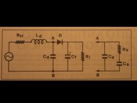
But, as you can see from the figure, you should put your slow-down capacitance, and the R-C snubber, on points A- B, BEFORE the diode bridge, to be effective. I have measured no difference while putting the snubber AFTER the bridge, on the filter capacitor.
No difference with respect to the classical snubbing, only.
And the noise generated this way, again, in a lucky situation, can be
so small, that not disturbing too much, so Carlos's snubber can operate in it's own, misterious way...
Phew, i don't believe, arrived at the end..
ciao, george
The best thing that I can do for illustrating this is to copy here a pic from that article, by Francesco Callegari. I do not know if it's possible. I would put that here now, and in case of any problems, moderators, please, could you remove it?
The transformer should recharge our reservoir capacitor. The audio circuit drains this capacitor, the transformer recharges. But it recharges in the form of short current pulses, not continously. When not recharging, it is disconnected from the rest of the circuit, more or less.
When not busy, he sits back peacefully, silently whistling a little tune..
Which tune will not be conducted directly to the audio circuit, but might be radiated, leaking across the diodes reverse capacitance, picked up by ground loops etc..
The transformer ideally should be a resistive impedance, reflecting the ideally low value resistive impedance seen by it 's primary... But it is not ideal, can be characterized by it's leakage inductance, and the capacitance of itself between it's own coils. Then there are the diodes, not conducting, but with there stray capacitance. These together form an L - C resonant circuit. If you hit such a circuit with some fast signal, it will be excited, and respond oscillating at it's resonance frequency. This all then will be radiated.
The fast signal is provided by the diodes, which are just shutting off. Their "addio" or farewell is a short spike or, in the best case, a small step. Then this spike & step will be happily refrained by the tank circuit.
Now, a signal with a fast rising edge, like a pulse or a step signal, rappresents a wide band noise, more or less evenly distibuted. The bandwidth is defined by the rising edge slew rate. A signal with several nanosec rising edge and ~ a volt amplitude means noise spectrum extending up to ~100 MHz. If we go back to 1 usec/volt, we are back in the 1 MHz range. If you are able to slow down that fast rising edge, you get lower freq. components in the noise, which then penetrate less the other circuits.
So, snubbing originally means slowing down these edges, by adding capacitance to the L - C circuit, making it more "lazy", and resonate at a lower freq. The R-C snubber then would even damp down the resonance peak.
This is a classic problem, the generated noise can be picked up by an AM radio, if you put it in the circuit's vicinity.
But, as we saw it here, if you use less lossy transformer, and much less spiky diodes, then you have only the small step function exciting the much less prone-to-resonate transformer. Even in this case you still have all this problems, so it might be useful still to do something, but in a much less scale, then with classic high current capability rectifier bridges, which are awful in this respect.
But, as you can see from the figure, you should put your slow-down capacitance, and the R-C snubber, on points A- B, BEFORE the diode bridge, to be effective. I have measured no difference while putting the snubber AFTER the bridge, on the filter capacitor.
No difference with respect to the classical snubbing, only.
And the noise generated this way, again, in a lucky situation, can be
so small, that not disturbing too much, so Carlos's snubber can operate in it's own, misterious way...
Phew, i don't believe, arrived at the end..
ciao, george
Attachments
Now a bit back to the previous -
Looked up the MBR760; MUR860 reverse junction capacitance. I have seen it well, the -schottky - MBR760 has 10 times higher values, then the MUR860. [10-20 pF with respect to 100 - 500 pF, in the 5V-40 V range]
Just a check..
Looked up the MBR760; MUR860 reverse junction capacitance. I have seen it well, the -schottky - MBR760 has 10 times higher values, then the MUR860. [10-20 pF with respect to 100 - 500 pF, in the 5V-40 V range]
Just a check..
Big Thanks for all this Joseph
I have followed your posts with great interest.
They confirm my spice and subjective findings that, even a single cap across the transformer secondary to reduce the frequency ( but not amplitude ) of resonance has a huge subjective effect of making following audio circuits sound more natural.
For the full snubber, I have found that 0.1uF in parallel with 1uF & 30 -100 ohms is a fairly standard cct that seems to work OK for most transformer / bridge ccts.
Do you have any thoughts on this idea that could mean that those people without your test equipment or the maths necessary, can make a pretty good job of a snubber cct using standardised values ?
(I suspect that the post bridge snubber cct that Carlos has developed has some special synergistic relationship with the chip cct that he is using it with - probably something to do with improving stability, gain / phase margin.)
cheers
mike
Carlos, I have a quick question for you :
Since you have built the regulated PS and this snubberized PS, in your opinion which one sounds better?
Thanks!
Since you have built the regulated PS and this snubberized PS, in your opinion which one sounds better?
Thanks!
mikelm said:Big Thanks for all this Joseph
(I suspect that the post bridge snubber cct that Carlos has developed has some special synergistic relationship with the chip cct that he is using it with - probably something to do with improving stability, gain / phase margin.)
cheers
mike
Hi
i've tried the snubbers on two classD amps (in the Carlosfm way ) , a Panasonic ( equibit ) and a UCD180 with Sikorel caps and they work...
the difference is immediately audible
alain
OK - thanks for this info - I will have to start some practical testing of Carlos's cct compared with my more comprehensive network.
interesting stuff
mike
interesting stuff
mike
rha61 said:i've tried the snubbers on two classD amps (in the Carlosfm way ) , a Panasonic ( equibit ) and a UCD180 with Sikorel caps and they work...
the difference is immediately audible
alain
This is an improvement to any high capacitance unregulated PSU IMHO.
Now it's Class D amps!😎 😎 😎
Thanks for reporting.
mikelm said:Big Thanks for all this Joseph
I have followed your posts with great interest.
SNIP
Do you have any thoughts on this idea that could mean that those people without your test equipment or the maths necessary, can make a pretty good job of a snubber cct using standardised values ?
SNIP
the equations from Hagerman's article, for an RC network across a single diode are;
R = SQRT (L/C)
where:
L is the secondary leakeage inductance
C is the lumped capacitance of the diode AND the interwinding capacitance.
just using a resistor across the diode is wasteful of energy, so a capacitor is placed in series with the resistor -- and to make it easy a damping factor for easy maths is employed:
C = (2 * PI * SQRT (LC))/R
i think that there are two reasons that snubbers are helpful -- damping ringing and radiated noise which can be coupled into preamplifying stages (or the VA stage of a discrete amplifier) , and secondly, saving energy -- the latter is trivial for a 50 or 60Hz line operated, non-switching supply designs but can cetainly affect efficiency in switchers operating at several hundred kHz.
I was thinking that the snubber would be across the secondaries rather than across the diodes.
I think this is what Joseph was talking about
putting a cap across the diodes seems a bit strange to me as you are connecting any AC noise straight into the supply.
mike
I think this is what Joseph was talking about
putting a cap across the diodes seems a bit strange to me as you are connecting any AC noise straight into the supply.
mike
Hi, Mikelm, all!
No, jackinnj stated it right - he refers [I think] the one rectifier model, what is visible in the figure that I had put up. So, there is one diode, but the cap is across the secondary, as shown.
You see, I was looking only at the effect and not digging into the particulars, how to optimize. But Jackinnj was doing it, so actually he could respond to You.
mikelm said:putting a cap across the diodes seems a bit strange to me as you are connecting any AC noise straight into the supply.
mike
Indeed.🙂
Hi jackinnj,
could you clarify what you had in mind so we can use your formulas with confidence
thanks
mike
could you clarify what you had in mind so we can use your formulas with confidence
thanks
mike
mikelm said:I was thinking that the snubber would be across the secondaries rather than across the diodes.
I think this is what Joseph was talking about
putting a cap across the diodes seems a bit strange to me as you are connecting any AC noise straight into the supply.
mike
well, Doug Self uses 100nF -- which, I think, is a number he pulled out of a hat.
If you have too large a snubber capacitor it will defeat its intended purpose -- in a low speed switching supply (like those based upon the ubiquitous SG3525) you can audibly hear the effect.
You can put the capacitor across the transformer secondary -- just model it this way in your sim program -- essentially Carlos has put the snubber across the secondary, although in his schematic it appears across the filter capacitors.
Mikelm, from the italian article, the author did the following:
had placed Ca, across the secondary; he used a value appropriate for arriving at around 20 -30 kHz of new resonance peak. He found that 110 nF serves well there. Then he calculated the optimum values for Rs, Cs.
That for Rs is the same what Jackinnj had put here:
He calls Ct, [totale] the resulting sum of Cd, Ca, that is, all the capacitance present // at the secondary;
Then Rs= 1000 * SQRT (Ld / Ct)
[ohm; mH; nF]
All the variables here are from that figure, lets call it figure1.
If you call that new resonance freq. at around 20 -30 KHz Fr3, then
Cs=10exp6 * Fr3 * Rs [nF; kHz; ohm]
I think this is exactly the same what Jackinnj had written.
Unfortunately no, Carlos had put the snubber on the wrong side, where it does nut snub, in effect. I consider this a fact, I was looking at it just too much. But, this way he discovered the Americas, just as Columbus did [wanted to say, like that another portuguese guy, but that's not true..🙂 ]
So, and here we are now, trying to find it out, what other way it might work!
But I fully agree with Mikelm & Carlos, that the cap across the diodes would just cause more problems.
So, and here we are now, trying to find it out, what other way it might work!
But I fully agree with Mikelm & Carlos, that the cap across the diodes would just cause more problems.
Mikelm, forgot to say, in that article, F. Callegari finally had arrived at 68 ohm; 680 nF. [He found his toroidal having .22 mH , per secondary]
He also found, that in systems with such a toroidal, and with a rectifier bridge it can be totally satisfying just to put 100 nF. With fast diodes the result was even better. [Caution! he was not using the bridges, that I had shown! he used 1N4007 as a start (a tube guy..)]
He also found, that in systems with such a toroidal, and with a rectifier bridge it can be totally satisfying just to put 100 nF. With fast diodes the result was even better. [Caution! he was not using the bridges, that I had shown! he used 1N4007 as a start (a tube guy..)]
Joseph K said:Unfortunately no, Carlos had put the snubber on the wrong side, where it does nut snub, in effect. I consider this a fact, I was looking at it just too much. But, this way he discovered the Americas, just as Columbus did [wanted to say, like that another portuguese guy, but that's not true..🙂 ]
So, and here we are now, trying to find it out, what other way it might work!
But I fully agree with Mikelm & Carlos, that the cap across the diodes would just cause more problems.
That'll be news to the engineering guys who write the PDF's at OnSemi, International Rectifier and ST Micro.
FWIW I have seen a number of circuits with "interference caps" (usually 200V/100nF types) from the secondaries to ground (center tap, then earth). This seems quite a standard arrangement, you see it quite a lot in application notes.
MBK
MBK
I think it very much depends on the particular diode and other circumstances.
If you have a run-of-the-mill diode that causes large switch-off transients, the cap may help to cure this more than the increase of the transmission of mains-borne junk.
With fast/soft recovery diodes, they may make things worse because there is not much switching transients to cure, while the mains stuff gets through.
And Jack, apps engineers are not immune to perpetrate "that's the way we ALWAYS did it" type of things..😉
Jan Didden
- Status
- Not open for further replies.
- Home
- Amplifiers
- Chip Amps
- Carlos' snubberized Gainclone Power supply