Hello everybody,
based on:
- the Baby Huey by gingertube;
- the shunt negative feedback;
- "A new look at positive current feedback" ( https://www.americanradiohistory.com/Archive-Radio-News/50s/Radio-News-1957-11.pdf page 56);
- "A new approach to negative feedback design" ( https://www.audiofaidate.org/it/articoli/Crowhurst_NewApproachFeedback.pdf );
- this thread ( GU-50 Push-Pull AB OT Impedance/Load Line Questions );
- this thread ( Bass Power Amp with GU50 );
- this link for g3 ( http://www.audioxpress.com/assets/upload/files/millet2903.pdf );
- and this link ( http://www.pmillett.com/tubebooks/tubedata/beam_power_tubes.pdf );
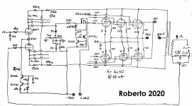
I came out with the attached schematic. It combines negative voltage feedback via shunt feedback with positive current feedback (well, it can be adjusted indeed) connected to the other side of the phase inverter.
Only one mosfet driver is shown, but there will be six, one for each power tube, with six bias controls.
470k and 150k are set to have a voltage drop from the B+ to have approximately 430V for the phase inverter.
I can use shunt feedback because the three GU50s, will have a rp of 8500/3 = 2834 Ohm and gm around 3x 5,5 = 16,5 mA/V.
What do you think about it?
based on:
- the Baby Huey by gingertube;
- the shunt negative feedback;
- "A new look at positive current feedback" ( https://www.americanradiohistory.com/Archive-Radio-News/50s/Radio-News-1957-11.pdf page 56);
- "A new approach to negative feedback design" ( https://www.audiofaidate.org/it/articoli/Crowhurst_NewApproachFeedback.pdf );
- this thread ( GU-50 Push-Pull AB OT Impedance/Load Line Questions );
- this thread ( Bass Power Amp with GU50 );
- this link for g3 ( http://www.audioxpress.com/assets/upload/files/millet2903.pdf );
- and this link ( http://www.pmillett.com/tubebooks/tubedata/beam_power_tubes.pdf );
I came out with the attached schematic. It combines negative voltage feedback via shunt feedback with positive current feedback (well, it can be adjusted indeed) connected to the other side of the phase inverter.
Only one mosfet driver is shown, but there will be six, one for each power tube, with six bias controls.
470k and 150k are set to have a voltage drop from the B+ to have approximately 430V for the phase inverter.
I can use shunt feedback because the three GU50s, will have a rp of 8500/3 = 2834 Ohm and gm around 3x 5,5 = 16,5 mA/V.
What do you think about it?
Attachments
AFAIK it's the opposite. Negative voltage feedback together with a small amount of positive current feedback has been used to have zero to negative output impedance.My only comment is your output nfb is measuring current rather than voltage. That will produce a high damping factor.
By saying that I would like more experienced people, I mean "than me" and I wouldn't say that you are not experienced, simply because I don't know you. No need to feel offended.That's OK I'll leave it to the 'more experienced people'
Here my friend, you have a voice and ideas, nobody needs to invoke more experienced people, if you believe that, you don't need to call anyone, just let them come.That's OK I'll leave it to the 'more experienced people'
If the honorable member believes their presence as well as value judgments to be necessary, he himself will surely create the conditions, both physical and electronic.
This is basically a DIY forum in which people from the highest elite converge as well as ordinary people who try and create their own threads and their own conclusions.
And of each of them, both the prestige or the brilliance of the idea, one or the other character may have the following or the interest of other members. In the meantime let this man come to his own conclusions who is excited about the subject. Furthermore, I am very interested in his findings.
Well everyone needs con ask other people's opinion, otherwise what a "forum" will do? This is a latin word that means "square", "public place", and it's where people was used to discuss. From there the virtual meaning where we are now.Here my friend, you have a voice and ideas, nobody needs to invoke more experienced people.
Thanks Esteban, I've just connected two dots that I'm sure others have connected before, I'm just looking for someone who already did something similar, to have some feedback.I know I lack alot of knowledge in power amp design (I'm a Mec.Eng.), so some hints can be helpful.Furthermore, I am very interested in his findings.
There are some points I would like to check before going into simulations, to learn doing it "the old way": Open loop gain and loadlines, optimising 12ax7 working point for the needed signal for the GU50s, calculate the needed minimum current for the drivers, then apply negative shunt feedback and recalculate, then positive current feedback and see how it goes at the end.
These last point will for sure need more experienced people than me to give some hints on how to. And I'll do. I've opened this thread more to learn how to design from scratch, rather than having everything ready to build it.
Hi Zintolo,
I believe that this 12AX7 PI may well provide enough gain, but not enough output voltage swing to drive those low gm GU-50's satisfyingly. I'd prefer something like a 6SL7 or 12AT7 instead and, depending on the desired input level for full drive and on the global NFB, add a voltage amplifier stage prior or past the PI.
Best regards!
Hi Kay,
thank you for the suggestion of the 6SL7 or 12AT7, I will try to simulate them. Unfortunately I don't have my RCA books with me, so I will need some help when going to manually calculate all parameters of the amp.
Yes, there will be gain stages before the PI in order to achieve the needed swing. I would like to keep the PI-to-speaker path as short as possible, so I will add the gain stages before.
I would like to do some calculations to check of things work, and get some confirmations on them. They are based on this post by Mona: EL84 Amp - Baby Huey
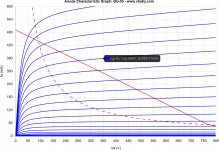
I've followed the reccomandations of having 280 V on g2, 150V on g3, 870 V on plates and a load Raa of 6 kOhm, even if it is constantly above the 40 W dissipation curve. This can be acceptable due to the fact that GU50s sere constantly forced ventilated, that half od the cycle are off and that bass instrument is played more with pauses rather than notes.
GU50s will swing from 870 down to 87 V when their grid will go from -46 up to +20 V. How dare is it to bring this amp in AB2? How can this be calculated?
That's a gain of 11,86.
Feedback is 470 kOhm / (150 kOhm / 2) = 6,27.
So on the 220 kOhm there will be 11,86 / 6,27 = 1,9 times the signal on g1(GU50) = a(ECC83).
The anode of the phase inverter sees (220 kOhm + (470 kOhm // 75 kOhm)) / (1,9 + 1) = 98,2 kOhm and the 1 MOhm (bias reference) in parallel.
So a total dynamic load of 89,4 kOhm.
Another option is to have 470 kOhm on the plates and the shunt as 220 k Ohm and 68 kOhm:
Feedback is 220 kOhm / (68 kOhm / 2) = 6,47.
So on the 470 kOhm there will be 11,86 / 6,47 = 1,83 times the signal on g1(GU50) = a(12AX7).
The anode of the phase inverter sees (470 kOhm + (220 kOhm // 34 kOhm)) / (1,83 + 1) = 176,5 kOhm and the 1 MOhm (bias reference) in parallel.
So a total dynamic load of 150 kOhm.
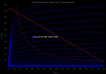
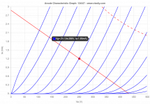
That would allow a better working point with 1,2 mA and Vgrid = -2 V circa, with a loadline from 423 V to 2,9 mA circa, swinging from 105 V when Vgrid = 0 to 380 V when Vgrid = -4 V, so totally 275 Vpp.
The gain of the stage is 275 / 4 = 68,8.
GU50s need (66 Vp x 2) x 1,9 = 250 Vpp, so we have some margin on the phase inverter.
The voltage drop across the 220 kOhm resistor of the feedback will be 220 kOhm x 1,2 mA = 264 V, so there will be 600 V on that side of the 470 kOhm resistor. This is not acceptable by the 12AX7, so this configuration cannot work.
Is there a driver that can work taking the shunt feedback from a plate at 870 V? Keeping the power amp in pentode mode, it would become mandatory to supply the phase inverter from a dedicated "UL" winding from the output transformer, with lower voltage supply on it? Will it work anyway?
EDIT:
uploaded 12ax7 loadline considering the second case.
I've followed the reccomandations of having 280 V on g2, 150V on g3, 870 V on plates and a load Raa of 6 kOhm, even if it is constantly above the 40 W dissipation curve. This can be acceptable due to the fact that GU50s sere constantly forced ventilated, that half od the cycle are off and that bass instrument is played more with pauses rather than notes.
GU50s will swing from 870 down to 87 V when their grid will go from -46 up to +20 V. How dare is it to bring this amp in AB2? How can this be calculated?
That's a gain of 11,86.
Feedback is 470 kOhm / (150 kOhm / 2) = 6,27.
So on the 220 kOhm there will be 11,86 / 6,27 = 1,9 times the signal on g1(GU50) = a(ECC83).
The anode of the phase inverter sees (220 kOhm + (470 kOhm // 75 kOhm)) / (1,9 + 1) = 98,2 kOhm and the 1 MOhm (bias reference) in parallel.
So a total dynamic load of 89,4 kOhm.
Another option is to have 470 kOhm on the plates and the shunt as 220 k Ohm and 68 kOhm:
Feedback is 220 kOhm / (68 kOhm / 2) = 6,47.
So on the 470 kOhm there will be 11,86 / 6,47 = 1,83 times the signal on g1(GU50) = a(12AX7).
The anode of the phase inverter sees (470 kOhm + (220 kOhm // 34 kOhm)) / (1,83 + 1) = 176,5 kOhm and the 1 MOhm (bias reference) in parallel.
So a total dynamic load of 150 kOhm.
That would allow a better working point with 1,2 mA and Vgrid = -2 V circa, with a loadline from 423 V to 2,9 mA circa, swinging from 105 V when Vgrid = 0 to 380 V when Vgrid = -4 V, so totally 275 Vpp.
The gain of the stage is 275 / 4 = 68,8.
GU50s need (66 Vp x 2) x 1,9 = 250 Vpp, so we have some margin on the phase inverter.
The voltage drop across the 220 kOhm resistor of the feedback will be 220 kOhm x 1,2 mA = 264 V, so there will be 600 V on that side of the 470 kOhm resistor. This is not acceptable by the 12AX7, so this configuration cannot work.
Is there a driver that can work taking the shunt feedback from a plate at 870 V? Keeping the power amp in pentode mode, it would become mandatory to supply the phase inverter from a dedicated "UL" winding from the output transformer, with lower voltage supply on it? Will it work anyway?
EDIT:
uploaded 12ax7 loadline considering the second case.
Attachments
Last edited:
That's what I said in #10: A 12AX7 won't do here as PI and driver simultaneously, cause it has enough gain, but can't provide the swing. A voltage amplifer between the 12AX7 PI and the finals is mandatory, preferably constructed around something like 12BH7, 6SN7, 6CG7 or similar.
Best regards!
Best regards!
Last edited:
According to me the load of the driver is 470k ÷(12+1) //150k÷2//220k//1M.
Thanks, can I ask you why?
Sorry , I am wrong . The 220k is in series. But then ,the feedback ratio is only 3.7% . You can adjust it to 10% by increasing the 150k .
Besides , you need to adjust the operating current . 1.25 ma ×(470k+220k)= 862 volts. To have it about 250v on the anode you need about 1ma.
Besides , you need to adjust the operating current . 1.25 ma ×(470k+220k)= 862 volts. To have it about 250v on the anode you need about 1ma.
Last edited:
Thank you Kay! Do you think a EF86 would do both?A voltage amplifer between the 12AX7 PI and the finals is mandatory, preferably constructed around something like 12BH7, 6SN7, 6CG7 or similar.
But.. is it ok to supply the PI from the plates? When One side is at 2 x Iccs the other side is at 0 current, so there's no voltage drop across the anode load and shunt fedback resistors, so there will be 870 V on PI's anodes, isn't it?
If so, can it be a solution to connect the voltage supply to the central point of the 75 kOhm resistor (so split it in two 38 kOhm), and insert two coupling caps between GU50's plates and the 220 kOhm shunt resistors?
- Home
- Amplifiers
- Tubes / Valves
- 450W bass amp: a sextet of GU50s with shunt¤t feedback