Thank you and also Happy New Year, a bit late but hey, right?Luka Happy New Year, happy to see you monitor this thread.
Most components are from K6 parts lists except the output filter(caps and inductor),IGBT, and feedback circuit.
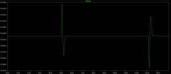
Step response is very good thanks to type III compensation, fsw (75kHz)
I will post LTspice simulation so you can play with it . all you will need to do is download LTspice(its free).
Is that your only scope? If you have any storage one, that step response would be great to post for others to see.
If not, by how much does it fall/rise going on and off load?
Still half bridge is it? what IGBT's did you go for?stewin
You are correct, but this is a prototype to test feedback,IGBT and a couple of small design changes I have made . The caps will be 2200ufd in the finish supply. the goal is for a 2kW supply.
stewin
You are correct, but this is a prototype to test feedback,IGBT and a couple of small design changes I have made . The caps will be 2200ufd in the finish supply. the goal is for a 2kW supply.
What will be the final voltage and current? What size amp into 8 ohms are you driving?
By the way GREAT WORK...outstanding

FB K6 revist
No this is FullBridge, the IGBTs are 12N60A4D(Fairchild) from ebay 2years ago and since the step response is mainly determined by compensating feedback I am attaching simulation of load stepped about 50% over 8mS, I have not tested real world because I am winding another inductor for 300uH and I am awaiting heat sink.
I don't expect real world response to be much different, LTspice simulator results have been very close in the past since it is for power supply simulation.
My scope is TEK 2230 which has storage and other handy features for switcher work.
Attachments
What will be the final voltage and current? What size amp into 8 ohms are you driving?
By the way GREAT WORK...outstanding

 welcome back chris after a very looooong long time
In the past I had constructed a halfbridge version of the A&T design and in this thread a few have tried with varying results so I decided to construct the FB version with some of my ideas to see if it would work out of the box if the instructions were followed and it does without problems with a different type feedback, I didn't use the feedback because I wanted the regulation tied to the positive rail and different circuit for the selected voltage outputs. I don't intend to power any amp this is only for testing for max output with the IGBT's.However when finished and performs as expected I will supply info for construction.
Last edited:
Those are nice, not bad at all. I used IKP15N65F5 in sine inverter, which have similar specs, a bit lower saturation voltage of CE. This will be interesting for surethe IGBTs are 12N60A4D(Fairchild)
Fairchild does not recommend these for new designs, there is a FBU replacement and they are sold on ebay for a good price but I have a few of the 12n's and will use them in feature projects, I am going to revisit LLC , I got turned off because of magnetics and PFC for the amount of power(2kW), Quasi FB seems like a good project.
Hi Guys,
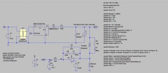
I found this schematic while scanning the whole thread. It was shared by member NRS, as I am looking for an smps circuit that has TL494 pwm IC, I got attracted to this one, parts is not too hard to find. Id like to get my hands on it, however there seems to be no details on TR1 and TR2. TR1 is a sensing traffo..? TR2 is a gate buffer.
Member NRS seems to be no longer in contact with DIYAudio (last visit was in 2015) I sent him/her a pm 2 weeks ago but no reply as of this posting.
Anybody out there knows how to construct TR1 & TR2..I could use s some help.
Thanks!
Albert
Attachments
TR! & TR2
The transformer (TR!) is more than likely a ETD44 core set / bobbin wound in the following manner 15 turns of primary, two secondary windings 7 turns each and finish with 15 turns of primary(use tape between windings, if you use other FSW then you will have to re-calculate turns of TR1.
TR2 is standard gate drive transformer costs about 5 to 6 US dollars each, check this URL:http://www.mouser.com/ds/2/336/-369999.pdf for info , you can wind your own (not hard check you tube for DIY gate drive transformers.
This circuit can be modified using gate driver IC's IR2010 or NCP5182 or others this will eliminate GTD and buffer transistors.
Hi Chas1,
Thanks for the feedback, ..guess I got confused with the traffo numbering, I meant T1 (not TR1) the other traffo connected to the lower half secondary of ETD44 tapped to the opamp 4558.
I plan to manually handwound the gdt, hopefully I could get it right I made one when I built a Detex clone (self oscillating topology).
Regards,
Albert
Attachments
I think, the time has come to move to better controllers than 494 or 3525 even for diy. Learning curve is the same as for this hard switching one, One thing in this thread that was never explore was regulation, what would be one thing to look into
Hi Luka,
I sent you a query pm regarding my self oscillating build that uses IGBT, it was originally designed for IRFP460 but I converted it for use with IGBTs. I followed the Fuji docs on how to implement it, it worked fine and looks powerful I however noticed an abnormal warming of IGBTs and gdt when powered without a load. I originally placed an 18vz for the gate protection but decided to backed it down to the usual 15vz because datasheets states gate saturation voltage is 15vz and temp goes down to a tolerable level, but anew problem emerges a noise is heard coming from the gdt traffo...a short burst of piercing noise like a grinder that accidentally hit a metal sheet..but with the 18vz gate zeners this noise is gone.
I do not have a scope that is one problem, so I asked is this a ringing effect at the gates? Could I try to use snubbers to eliminate the noise? It is working fine even with this noise at power on, regulation looks good, no voltage drop I could crank up the volume powering a 2 channel P3A amp. It just worries me. Sorry I was insisting on asking questions from an old smps topology it was a build that I could complete at the moment with all the parts taken from discarded boards.
My setup:
10r gate limiting resistor
GUR460 anti-parallel diodes (across gate & emitter)
10k (also across gates & emitter)
15vz back to back (gate protection diodes)
EE19 gdt (no pwm IC)
Albert
(Got your reply at the time of this posting. Thanks!)
Last edited:
Follow up query for the smps gurus..")
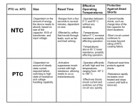
Could I use PTC thermistor in line with the primary high side (+ rail) just after the bridge rectifier? I am thinking of a cheap short circuit protect that could act instantaneous when a fault happens inside the circuit. I am hesistant on using NTC because their resistance starts high during a cold start up. I am aware that the common practice is to install them right at one of the AC mains line entry but I've seen some circuit that had it connected after the bridge rectifier. Is this effective enough?
Could I use PTC thermistor in line with the primary high side (+ rail) just after the bridge rectifier? I am thinking of a cheap short circuit protect that could act instantaneous when a fault happens inside the circuit. I am hesistant on using NTC because their resistance starts high during a cold start up. I am aware that the common practice is to install them right at one of the AC mains line entry but I've seen some circuit that had it connected after the bridge rectifier. Is this effective enough?
Attachments
more photos on the project .
Music and a nice climate, can you give a piece of the equator to us in holland?.
It is cold here and I do not like that (joint atrosis).
Music and a nice climate, can you give a piece of the equator to us in holland?.
It is cold here and I do not like that (joint atrosis).
yeah but good thing are loading ............
- Home
- Amplifiers
- Power Supplies
- Offline full-bridge SMPS… need help