BTW the 0.6nV/rtHz is the same that Kozard had with his LNA which I believe is similar to yours. So that sounds reasonable.
That is good to hear. I used the denoiser in the supply for previous measurements but I used the dienoiser option for the last measurements of my discrete supplies + denoiser which I posted on their own thread. I figured I should enable it maybe it helps, since the collectors of the BJTs are tied to the negative rail through a RC filter which offers I think around -30dB PSRR or so at 50Hz.
@bohrok2610
Here is the LNA with a 1k resistor soldered on the input cable.
View attachment 923290
How do I get 4nV of noise from this plot?
Couple of more notes on this. In post #343 the "FS sine Vrms" is set to 9.947 and in post #347 it is set to 0.194. Should the latter number actually be 0.009947? (which I assume REW rounds to 0.01)
Since most soundcards have rising noise floor below 10Hz and above 30kHz it makes sense to use high and low pass filtering (set at Distortion settings in REW). You might also consider using lower sample rate (e.g. 48kHz) for the same reason.
I managed to measure my V1.4 board with LM337N from TI. The board is the version for LM317 but the only physical difference between the LM317 and LM337 version are the two in/out pins of the regulator, traces are different slightly to account for the reverse in/out pins, else everything is identical. I put the LM337 on the back of the board.
- The output capacitor is a Panasonic FR 470uF/25V with part number EEU-FR1E471LB. I recommend this capacitor for any LM337 +denoiser or dienoiser.
- Compensation network was 1x22nF + 2x10nF caps sandwiched, no R. I can't guarantee this value will work on other boards. But if you want to try add a 1R also. I was lazy to add it, I usually do. Seems to work fine without it for me.
- Input voltage around 18V, input caps 1x470uF and 1x100uF in parallel. 200R/1600R resistor combo for LM337 output voltage setting.
- 150R load resistor.
I also poked at the different denoiser nodes with metal tweezers and seems to recover nicely and fast.
I made a zip file with each individual measurement with the value of the signal of interest. The files with the N_ prefix are of the dBV/√Hz measurements. I attached here just two photos so to not be cluttered, and I overlayed all measurements in each.
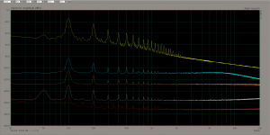
The first photo is of PSRR measurement. I set the scale to dBV this time, I also added the 1000x gain, I used 1x gain for the input ripple measurement, I connected the ADC directly to the filter cap through a 47uF cap.
The traces in the photo are as follows from top down:
- yellow trace - input ripple
- cyan trace - normal LM337
- orange trace - LM337+Cadj
- grey trace - LM337 + denoiser
- red trace - LM337 + dienoiser
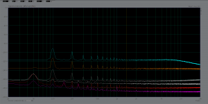
Second photo is in dBV/√Hz and traces are as follows from top down:
- cyan trace - normal LM337
- orange trace - LM337+Cadj
- grey trace - LM337+denoiser
- white trace - 1k resistor
- red trace - LM337 + dienoiser
- magenta trace - LNA input grounded.
As seen in each individual measurement photo, the LNA noise/1k resistor match in previous values with 1300mV set in ARTA for 0dB.
I will look into REW as well as I'm curious. I might also need a better soundcard.
- The output capacitor is a Panasonic FR 470uF/25V with part number EEU-FR1E471LB. I recommend this capacitor for any LM337 +denoiser or dienoiser.
- Compensation network was 1x22nF + 2x10nF caps sandwiched, no R. I can't guarantee this value will work on other boards. But if you want to try add a 1R also. I was lazy to add it, I usually do. Seems to work fine without it for me.
- Input voltage around 18V, input caps 1x470uF and 1x100uF in parallel. 200R/1600R resistor combo for LM337 output voltage setting.
- 150R load resistor.
I also poked at the different denoiser nodes with metal tweezers and seems to recover nicely and fast.
I made a zip file with each individual measurement with the value of the signal of interest. The files with the N_ prefix are of the dBV/√Hz measurements. I attached here just two photos so to not be cluttered, and I overlayed all measurements in each.
The first photo is of PSRR measurement. I set the scale to dBV this time, I also added the 1000x gain, I used 1x gain for the input ripple measurement, I connected the ADC directly to the filter cap through a 47uF cap.
The traces in the photo are as follows from top down:
- yellow trace - input ripple
- cyan trace - normal LM337
- orange trace - LM337+Cadj
- grey trace - LM337 + denoiser
- red trace - LM337 + dienoiser
Second photo is in dBV/√Hz and traces are as follows from top down:
- cyan trace - normal LM337
- orange trace - LM337+Cadj
- grey trace - LM337+denoiser
- white trace - 1k resistor
- red trace - LM337 + dienoiser
- magenta trace - LNA input grounded.
As seen in each individual measurement photo, the LNA noise/1k resistor match in previous values with 1300mV set in ARTA for 0dB.
I will look into REW as well as I'm curious. I might also need a better soundcard.
Attachments
Last edited:
Based on your noise measurements your denoiser has about 7nV/rtHz@1kHz and the dienoiser has about 1.3nV/rtHz@1kHz which match quite well to what both Tombo56 and myself have measured (see e.g. here). So apparently both Tombo56 and myself are capable of making satisfactory denoiser layouts 
One note on your measurements. When measuring noise there really is no need to have any ripple on input. So you could use e.g. battery voltage as input.
One note on your measurements. When measuring noise there really is no need to have any ripple on input. So you could use e.g. battery voltage as input.
I do not claim that I am one of the few that could do it. I just want to make sure as I know there's some things to consider for good results.
I'm glad that the measurements match. I have to get into REW as well and see what's what.
Regarding the noise yes, I was lazy and I did them while everything was already connected.
Would a lead acid battery do?
I'm glad that the measurements match. I have to get into REW as well and see what's what.
Regarding the noise yes, I was lazy and I did them while everything was already connected.
Would a lead acid battery do?
So you think layout is a potential cause of the neg reg issue of RickRay's build?So apparently both Tombo56 and myself are capable of making satisfactory denoiser layouts
I fixed the issue with the negative rail in the Hafler DH-110. I have no idea what it was, must have been a bad solder connection. I removed the transistor and diode from the board and was able to test all other components with these removed. Tested transistor and diode they were good so reinstalled and viola, it worked.
Couple of more notes on this. In post #343 the "FS sine Vrms" is set to 9.947 and in post #347 it is set to 0.194. Should the latter number actually be 0.009947? (which I assume REW rounds to 0.01)
Since most soundcards have rising noise floor below 10Hz and above 30kHz it makes sense to use high and low pass filtering (set at Distortion settings in REW). You might also consider using lower sample rate (e.g. 48kHz) for the same reason.
When you input .001 it never displays .001, it changes to what the full scale reading would be and it changes every time you input .001.
Try it yourself, just type in .001 and watch the display value change.
So you think layout is a potential cause of the neg reg issue of RickRay's build?
My suspicion is a ESR correcting resistor if present. That should be removed and replaced with a piece of wire, or shorted directly. It has no place there on the negative rail output capacitor. That capacitor should have a total ESR of maximum 50mOhm.
What capacitor is used for the negative rail output? Value is not important, ESR is, and that dictates the stability. That is the first thing towards having a stable LM337 + denoiser.
So you think layout is a potential cause of the neg reg issue of RickRay's build?
Layout may of course have some impact but I would not expect that to cause uniform wideband increase to noise. I would first remove (i.e. short) the resistor in series with the output capacitor (ESR correction resistor as Trileru calls it).
Also the resistor in series with the compensation cap (R14) may degrade the performance.
Last edited:
Also the resistor in series with the compensation cap (R14) may degrade the performance.
Same thing on the positive side (remove and short R13).
Last edited:
- Home
- Amplifiers
- Power Supplies
- VRDN: bipolar regulator PCB for line level ckts: ±11V to ±20V @ 1.5A with "De-Noiser"