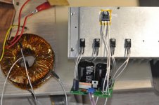
But what about Q1 MJE15030G. How you think - does it make sence to take care of it? Place it on computer case wall, even it will be 2A 5V?
Q1 is a good size driver that burns about 200mW even when 5A passes Q2 so its not normally in danger. If you feel its in a hot place by other parts radiation and no good ventilation just measure its tab temperature with a contact probe. If often above 75C in your build put a mini clip-on TO-220 sink on it for better long term reliability.
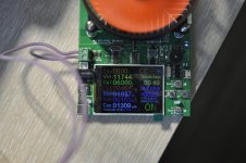
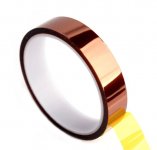
That's a good deg thermal exchange state for 13minutes on 6A punishing CC electronic load. Will be even better when the fins stand right. Lets hope Kapton tape will last long as insulator in the build. Voltage drop is measured at the load I see, no Kelvin sense wires back to the output connector, so its real life including the output cables drop.
Correct practice experimenting with the meant to install cables length and thickness knowing the voltage tolerance to expect at their end between lowest to highest projected target load current.
Correct practice experimenting with the meant to install cables length and thickness knowing the voltage tolerance to expect at their end between lowest to highest projected target load current.
The author of this feedback pair transistors circuit was a renowned US engineer of Hungarian descent.
I have heard it as Ziklai without S and the emphasis on the a in klai like we pronounce dai in Hyundai.
Could also be sZiklai with a soft s before Z and an emphasis on the first i in Hungarian.
I have heard it as Ziklai without S and the emphasis on the a in klai like we pronounce dai in Hyundai.
Could also be sZiklai with a soft s before Z and an emphasis on the first i in Hungarian.
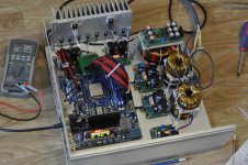
Yes, I took them ready and twick them for needed voltages.You wound the toroids yourself
5x L-Adpater in case...
What are the output values and what do you plan to do with this setup?
Using the GPIO's 5V pins & GND pins allows for thicker and even doubled up power cables so it could be beneficial for minimizing voltage loss when pulling current peaks in heavy peripheral and/or demanding software configurations.
In Pi4 there is no resettable fuse either via USB or GPIO powering I think, so there's no extra safety difference, but double check on that info.
In Pi4 there is no resettable fuse either via USB or GPIO powering I think, so there's no extra safety difference, but double check on that info.
Hello,
Question of a newbie here...
I compleated the build and I'm facing a problem.
Used a 30VA 9v Tx
So I'm getting up to Jumper position No7 and I get 7 Leds lit and about 11.48v with the trimmer at max.
After that for the next two jumpers I get no leds on and I keep geting a constant voltage of 11.58 with no variation when adjusting the trimmer. The same readings and behavior as if I have no jumppers at all.
Any ideas?
Thank you very much
Spyros
You go up to max transformer potential but that is normal. Critical is, can you set different levels below 10V L-Adapter output with that 9V transformer? If yes, your build works and you will find different transformer potential recommendations for different enough Vout ranges in the PDF guide, post#1.
To quote from the guide for anyone reading our conversation and wondering:
1. For 2.5V-3.3V output rail use 7V transformer. For 5V-6.3V rail 9V Tx. For 7.5-10V rail 12V Tx. For 12-14V rail 15V Tx. For 15-18V rail 18V Tx. For 19-20V rail 20V Tx.
2. Select 2 times more VA transformer spec than the load Watts when for below 14V rail. For example a 5V 2.5A RPi rail is 12.5W peak capable. Thus don't use smaller than 25VA transformer. In higher than 14V rail voltage cases use 1.5 times more VA than load Watts
I finished an L-Adapter board and fired it up and it worked. The voltage was low, only reading 7+ volts with jumper at J5 and 26 VAC applied to AC inlet. I went to check the voltage at the inlet and as soon as I did that the primary fuse blew.
Now I cannot get it to stop blowing with the PSU connected to the secondary windings. I checked and made sure that all the diodes and Q2 are not shorted to the chassis. The fuse I had on the primary was a 2A fast blow.
I am running 120V AC with a 300 VA transformer with 26 VAC secondary. My target voltage was 19VDC @ 3.5A What value should my primary fuse be? I suspect it needs to be slow blow but maybe the current rating is too low. Where did I go wrong?
To properly fuse a 300VA 120VAC mains transformer it takes a 5A slow blow on its primary side. To withstand its momentary magnetic buildup inrush.
There's substantial reservoir capacitance on the L-Adapter pulling charge up inrush current for a little bit longer too.
26VAC secondary maybe too plenty for 19VDC 3.5A reg out. Can add some unnecessary Q2 dissipation. See how much raw DC is made across the reservoir caps and if they are well rated for it.
Why you only saw 7V+ initial DC output I am not sure since you didn't find something obvious in the rest of the circuit yet. Try set J8. Check if healthy Vbe on the driver and pass transistors first and also see not to have oriented any caps or the diode (D11) wrong. R3's value should be checked too.
- Home
- Amplifiers
- Power Supplies
- L-Adapter


