good, but I mean roughly L-Adapter have 50% efficient. So for 50W usefull load it must the same 50W heat dissipation. It is look like small CPU with normal cooler. Am I right?
More than 50% around 70-75% depending on how close for loss voltage across you configure it. In any case it can usually cover small CPU applications like Pi computer audio with relatively small Q2 sinking.
I understand, about Pi computer, ODROID and so on it is no questions.
But I wanted to power simple micro ATX board with low power Xeon CPU + 21W Video card GT710. I has several L-Adapter boards.
Now testing +12V power for CPU. Tested: 1) 14V transformer, 2) 16V transformer, 3) 1A and +12V load, 4) 2A and +12V load. Always 50% efficient. I could use very large radiator, but if it could be 70-75% efficient (as you said), all will goes much much better.
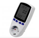
Comparing what the mains power meter shows with how much power the application seems drawing its maybe not pure heat loss on the sinks as it can also be AC power factor loss. "In an electric power system, a load with a low power factor draws more current than a load with a high power factor for the same amount of useful power transferred." Better judge on how much heat by deg C on sinks than from apparent power on the AC mains meter minus expected DC power for the computer.
Power factor - Wikipedia
*When on peak load current the DC input voltage to Q2 is just 2.5V higher than the output voltage, the L-Adapter's DC power efficiency is usually at its highest.
Power factor - Wikipedia
*When on peak load current the DC input voltage to Q2 is just 2.5V higher than the output voltage, the L-Adapter's DC power efficiency is usually at its highest.
I understand. But for my case, general CPU and motherboad, 2.5V differance is a bit high. By specs for ATX power it must be for +12V:
+12VDC: ± 5%, from +11.4V to +12.6V
Transformer now has 16VAC, capacitors 2x10000uF. I tried no load: 12.5V (it is ok for ATX specification). Then 1A load => 12V, also good. But for 3A it is 10.5V. How I could get more stable Vout? Raise transformer secondaries up to 18V or set larger capacitors = 22000uF or more? What you suggest for 4-5A?
Last edited:
Losing 1.5V output over a 2A difference step suggests 0.75 Ohm output impedance. Not the case in a properly executed and properly configured L-A. You should check two things each time.
First how much DCin to Q2 is eaten by Tx AC drop, Vf drop on bridge diodes, and AC ripple on filter caps i.e. pure DC Vin-Vout margin should not drop below 2.5V across D11. Second thing is that the loss over the output cables to the computer does not eat more than allowed. Read post#149 carefully as well as the "How to plan it" section in the L-A's pdf manual. Explaining how to predict, measure, and tackle those issues. Assuming that your L-A works as it should. Is it an original board or your development?
First how much DCin to Q2 is eaten by Tx AC drop, Vf drop on bridge diodes, and AC ripple on filter caps i.e. pure DC Vin-Vout margin should not drop below 2.5V across D11. Second thing is that the loss over the output cables to the computer does not eat more than allowed. Read post#149 carefully as well as the "How to plan it" section in the L-A's pdf manual. Explaining how to predict, measure, and tackle those issues. Assuming that your L-A works as it should. Is it an original board or your development?
Is it an original board or your development?
Salas, as general - my development 🙂. I didn't solder Fuse F1, is it critical? You use it as part of CRC filter.
Last edited:
You did the IC1 R2 tricky connections right but you mixed up the easy bit on Q2. Happy end, you found the error.
How you sink it now? Its in a difficult place. You put it on a large external sink with cable extensions on Q2 pins?
You skipped the fuse, is there a D11 reverse voltage protection diode at least? Is there a jumper row? Can't see.
How you sink it now? Its in a difficult place. You put it on a large external sink with cable extensions on Q2 pins?
You skipped the fuse, is there a D11 reverse voltage protection diode at least? Is there a jumper row? Can't see.
Yes. Two of your boards: UltraBib and L-Adapter. In both made 1 error per board. Not bad for newbie. But for me it is a bit pitty, because I rechecked those boards several times.You did the IC1 R2 tricky connections right but you mixed up the easy bit on Q2. Happy end, you found the error.
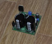
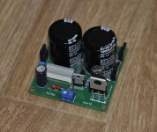
Yes, extensions wires, there are no other variants. It will be very huge radiator inside PC case + 140mm coller on top for all PC components (mother board, CPU, L-Adpater's and so on). The most hotest elements on 5A current are diods rectifiers FFPF30UP20STU. For L-Adapter's motherboard (where will be low GPU) and CPU, all hot elements will be on radiator: NJW0302G, MJE15030G, FFPF30UP20STU. Other L-Adapters will be will general radiators on board.How you sink it now? Its in a difficult place. You put it on a large external sink with cable extensions on Q2 pins?
Fuse did not developed on this board, but D11 exists.You skipped the fuse, is there a D11 reverse voltage protection diode at least? Is there a jumper row? Can't see.
Last edited:
4.5V*5A=22.5W dissipation on Q2 at times and you have to cool the bridge diodes too. Around 8A RMS is a logical max usage that is why I have 8A Slow Blow fuse in the BOM. You can even try to parallel L-Adapters for even more Amperes.
I don't need more amperes. I think all system will consume 40W or less. It will be splitted on 5 L-Adapters.
By the way, on no load it is 4.1W usage for L-Adapter. A bit greedy beast 🙂
By the way, on no load it is 4.1W usage for L-Adapter. A bit greedy beast 🙂
Its the bridge rectification on Tx loss and AC power factor loss added to what DC state loss there is. In DC domain only it isn't that greedy. Its as greedy as an LM317. But more powerful. Use thickest practical output cables to the computer. 5A isn't little to pass.
*If you would use an SMPS DC output to L-Adapter than Tx and bridge diodes it would show more efficiency as a combo but that goes against the full linear PSU quality logic of using an L-A in the first place.
*If you would use an SMPS DC output to L-Adapter than Tx and bridge diodes it would show more efficiency as a combo but that goes against the full linear PSU quality logic of using an L-A in the first place.
About thick cables to computer I agree with you.
Right now I rearange L-Adapters in computer lage case. Two Q2 will be on large radiator and other on case walls.
But what about Q1 MJE15030G. How you think - does it make sence to take care of it? Place it on computer case wall, even it will be 2A 5V?
Right now I rearange L-Adapters in computer lage case. Two Q2 will be on large radiator and other on case walls.
But what about Q1 MJE15030G. How you think - does it make sence to take care of it? Place it on computer case wall, even it will be 2A 5V?
- Home
- Amplifiers
- Power Supplies
- L-Adapter


