I reduced the VA to 200 and used a 3.25A Slow Blow fuse.
The caps are 6800uf 35V
I probably should've used 10,000uf I have some just is case it's an issue. I just didn't want to desolder them.
Thanks on the meter! I figured for a few dollars, why not?
You measured 29V rectified DC with this transformer so there is ample space for heavy load AC ripple to eat away DC until 21.5V (19V you set + 2.5V threshold of minimum advised margin). Your 6800uF caps should do well in those conditions. Lowering the bridge's peak current and dissipation when using less than you could, but still enough uF for a job.
In the final application phase perform two simple measurements:
-When the front panel meter shows max load amperage, monitor that the DC drop across D11 is not below 2.5V. Else up the reservoir caps uF.
-At max load amperage again, measure DC out after umbilical on the pins of the load's end connector. So to know voltage loss in the cabling at peak consumption. See if end DC out is still within the minimum input voltage spec of the gear you power.
If not, you can compensate some loss via the trimmer but not much, not letting rise above max input voltage spec of the loading gear when at cruising consumption level.
Guys, need quick help here. Facing some strange issue.
I got this transformer
AS-1209 - 100VA 9V Transformer - AnTek Products Corp
I connected green to green and Blue to Blue to make a parallel connection (I stripped copper wires though so that these can go into the Molex hole).
I should get 18 Volts AC on Molex solder joint, right? But I just checked AC on Molex solder joint, it is giving me 9.3 Volts only. Am I missing something here?
Power supply output is also max going to 9 - 10 volts DC with dim Led panel.
Can someone please help me here?
Thanks,
Simar
@Salas
I have just completed assembly of my latest Rpi4 and USB DAC project using your L Adapter design and product supplied by Teabag. The L Adapter and UltraBiB are my key building blocks for DC power requirements and have proven to be very reliable. Thank you for sharing your skill and expertise.
Attached is a picture of my latest build with the Allo Revolution Dac and Rpi4. The heat sinks are my solution due to real estate issues within the enclosure. Regards.
Attachments
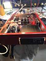
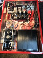
You are welcome. Happy when designs give practical & reliable solutions to fellow members. You applied some interesting sinking combinations indeed. You even use a TO-264 package Q2 in the back L-Ad I see. Is it 2SA1943 or MJL1302A? I also see incoming black wires there but I don't see a second transformer. Spliced to the blue and brown secondary wires? How many VA is the photo's transformer and is it staying at an acceptable temperature?
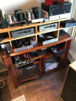
For this particular implementation I use a dual secondary transformer (35VA) which feeds two instances of the L Adapter. One adapter uses NJW0302G for Q2 and the other uses 2SA1943. I use aluminium oxide thermal pads to characterize the heat dissipation for this particular enclosure since this unit will be left on 24/7. Initial power up sequence is Dac is on first when plugged in and then the Rpi4 switched. For system survivability I have similar power supplies so I can switch power easily for testing within the unit itself and also the other units in my listening eco system. Heatsink temperature is about 42 deg C and transformer is 35 deg C. Attached is a picture of my system. Regards.
Attachments

You measured 29V rectified DC with this transformer so there is ample space for heavy load AC ripple to eat away DC until 21.5V (19V you set + 2.5V threshold of minimum advised margin). Your 6800uF caps should do well in those conditions. Lowering the bridge's peak current and dissipation when using less than you could, but still enough uF for a job.
In the final application phase perform two simple measurements:
-When the front panel meter shows max load amperage, monitor that the DC drop across D11 is not below 2.5V. Else up the reservoir caps uF.
-At max load amperage again, measure DC out after umbilical on the pins of the load's end connector. So to know voltage loss in the cabling at peak consumption. See if end DC out is still within the minimum input voltage spec of the gear you power.
If not, you can compensate some loss via the trimmer but not much, not letting rise above max input voltage spec of the loading gear when at cruising consumption level.
The voltage across D11 is 9.1V. This is ok right?
The voltage across D11 is 9.1V. This is ok right?
It's more than enough for Q2. But this is a not loaded/light loaded measurement, right?
It's more than enough for Q2. But this is a not loaded/light loaded measurement, right?
At no load it's 10.2V
At 27% it's 9.1V
I'll run a CPU stress test tonight, I think that will show 60% load. I need to get a resistor to simulate above that. I spec'd the current at 3.5A because I will upgrade the processor soon and I suspect that will increase the load. Right now this is with a Intel Core I5, I'll be moving to a Core I9 soon
0.95A on the panel. That's about what it's been running at when I stream music or listen to tracks on the hard drive. If I surf the web at the same time it will jump to 1.7A and at start up it draws just under 2.0AWhat current your panel meter shows at 27% CPU?
The panel meter has I_Adj and V_Adj trimmers at its back to can correct readings if bit inaccurate? By comparing them to some known good accuracy DMM I mean.
Mainly useful to correct when powering low input voltage spec gear where readout error and cable voltage drop matter more. For example a 0.1V display error is 2% wrong in a 5V application but only 0.5% wrong in a 19V application like yours.
Mainly useful to correct when powering low input voltage spec gear where readout error and cable voltage drop matter more. For example a 0.1V display error is 2% wrong in a 5V application but only 0.5% wrong in a 19V application like yours.
Hello Mr Salas,
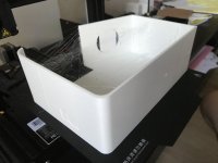
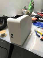
Thank you for the excellent circuit that you have shared with us. I have built it and housed it inside a 3D printed case and the circuit has proven to be very reliable, supplying a RPI4 running Moode with a hard disk connected to it. Not problems at all even when playing DSD tracks.
Really appreciate your kindness in sharing your expertise!
Attachments
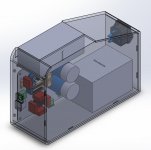
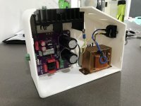

Very nice 3D printed housing. Congratulations. That full bridge can not be on a sink as implemented and will have a lower dissipation limit than the TO-220 diodes on sinks. The original board sees to can also cover the odd very heavy loading stuff.
But to known moderate loads this integrated bridge allows for a "squarer" PCB. So all well in your application.
Did you ever compare supplying your rig with a typical SMPS adapter and did you get a discernible difference with this linear PSU?
But to known moderate loads this integrated bridge allows for a "squarer" PCB. So all well in your application.
Did you ever compare supplying your rig with a typical SMPS adapter and did you get a discernible difference with this linear PSU?
Thank you Mr Salas for your kind words!
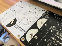
I made full bridge rectifier boards to go with your L-Adapter and on the L-Adapter, there is provision for the square rectifier to be bypassed. The boards are the same size hence they can be stacked nicely if needed to.
Previously I was using the RPi's Official USB-C supply. I felt that the difference was obvious to me and that L-Adapter powered RPi4 sounds "calmer". What are your findings about the sound of L-Adapter?
Attachments
My findings are it makes a difference to a bolder calmer sound even to very well internally regulated rails DACs maybe because no external SMPS noise intrudes through their grounding paths anymore. With computers it makes a difference also, smaller but similar, maybe because everything hooks up to them and they allow noises to be shared through their ground.
Most spectacular transformation was when a friend performed a demo to me with original SMPS vs L-Adapter he built for powering a Logitech Squeezebox Touch streamer driving his Benchmark DAC3.
The moment he exchanged SMPS to L-Adapter on the Squeezebox, sound went from local league to super league. Something was "holding back" the performance before. Being an older lower cost streamer it was more sensitive to external PSU quality it seems.
- Home
- Amplifiers
- Power Supplies
- L-Adapter