Finally done with assembly. Thanks, Salas for the great design. Running RPi 3 and Allo Boss DAC hat. The bass is much smoother and tighter. I was having distortion problems at higher volumes with this setup, which went away after using L Adapter Linear Power Supply. Kudos. 🙂
One quick query Salas, I am planning to add Voltmeter to chasis. Something like this. Is it fine, will it have any effect on DC output? Should I attach this directly to the DC output Molex Connector?
DIY Red Blue Digital LED Mini Display Module DC2.5V 32V DC0 100V Voltmeter Voltage Tester Panel Meter Gauge for Motorcycle Car|Voltage Meters| - AliExpress
Thanks,
Simar
Attachments

Hey, nice to know it benefits your digital rig. Well made wooden box. Ventilation holes above the sinks area a must if using a lid. A metal mesh top would look good by the way. Red LEDs light escaping it in a darkened room is warm.
About a digital panel voltmeter parallel to the Molex output connector I don't see a problem. It is usually high impedance and asks for too little energy. Non intrusive. Unless it could make or attract some little noise (?).
Just for peace of mind that the particular meter is no detriment to quality, test it before making a box cutout for fitting. If everything works fine and sounds as good as before, go ahead and install it.
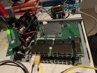
It has been a while since i visited DiyAudio but i am am very happy with the L-adapter. I have 4 of them powering a DAC, 2 network switches and my internet router. Very happy with the upgrade in SQ.
The switches have their SMPS removed and i use LT3045 regulators after the L-adapter to go from 5V into 3.3, 2.5 and 1.2V.
Now i have a challenge i am not yet sure how to solve. I will get new network switches end of November. These Buffalo BS GS2016 switches will get their 12V SMPS removed and I would like to replace the onboard converters by regulated power supplies. Looking at what others found it seems that 3.3V and 2.5V do not require much current. The challenge is the 1V supply that probably needs 5-6A!. Is this something that can be achieved by the L-adapter or should I look for another solution or forget about this?
regards
Harold
Hi
Just an idea:
LA starts from about 1.5V setting. Say you put a powerful diode in series with the load and it should bring Vo down by some adequate amount of forward voltage drop for your 1V application. LA has a trimmer and you can fine tune the result with that diode. I would do that with a dummy load mimicking the actual load current need first.
Hi
Just an idea:
LA starts from about 1.5V setting. Say you put a powerful diode in series with the load and it should bring Vo down by some adequate amount of forward drop voltage for your 1V application. LA has a trimmer and you can fine tune the result with that diode. I would do that with a dummy load mimicking the actual load current need first.
Thx for the quick reply. A diode would give me 0.7V drop (or more in series). Would that voltage drop be constant or would it depend on the load? But i guess that could be experimented with the dummy load e.g. a 0.2Ohm 10Watt resistor.
What about a zener or a voltage divider?
regards,
Thx for the quick reply. A diode would give me 0.7V drop (or more in series). Would that voltage drop be constant or would it depend on the load? But i guess that could be experimented with the dummy load e.g. a 0.2Ohm 10Watt resistor.
What about a zener or a voltage divider?
regards,
I see that the foward voltage depends on load (current) and temperature. If the load would be constant then i would need to put the diode on a large heatsink to keep the temperature within control. Probably set the exact voltage in the L-adapter at operating temp. The switches are always on so that is a matter of waiting for some temp convergence. I am not sure how constant the load is of this 1V line.
You would have to choose some fancy TO-220 sink mountable diode and experiment I guess. If the 1V switch has some +/- % Vcc margin spec it should not be bothered by the diode's Vf drop range vs the load current range passing.
As for how much of a constant pull is that 1V line try measure it with the DMM in series 10A scale and push the min/max button to catch range.
About voltage division with resistors it's they should be of really small values not to add much output impedance but that will make them pull and dissipate serious power.
Same for a Zener it needs a series protective resistor and it will shunt power itself but it's also a further noise source that may bother the switch or not.
You would have to choose some fancy TO-220 sink mountable diode and experiment I guess. If the 1V switch has some +/- % Vcc margin spec it should not be bothered by the diode's Vf drop range vs the load current range passing.
As for how much of a constant pull is that 1V line try measure it with the DMM in series 10A scale and push the min/max button to catch range.
About voltage division with resistors it's they should be of really small values not to add much output impedance but that will make them pull and dissipate serious power.
Same for a Zener it needs a series protective resistor and it will shunt power itself but it's also a further noise source that may bother the switch or not.
I think i will experiment with the diodes. What would be the voltage of the trasnformer for the L-adapter. Somthing like 5V?
Yes, possibly 5V. Depends on how much of raw DC is going to be lost as AC ripple if the amperage is high. There are some strong current 6.3V transformers for tube filaments also.
I guess I have to contact Teabag for some additional L-adapter kits 😉
6.3V trans --> L-adapter --> 3.3V -->3.3V rails
3.3V -->LT3045 regulator --> 2.5V rail
6.3V trans --> L-adapter --> 1.5-2.0V --> 1 or 2 diodes --> 1V rai
Something like this
6.3V trans --> L-adapter --> 3.3V -->3.3V rails
3.3V -->LT3045 regulator --> 2.5V rail
6.3V trans --> L-adapter --> 1.5-2.0V --> 1 or 2 diodes --> 1V rai
Something like this

Heavy experiment!
Twenty years ago I asked the NOC administrator in an ISP company a naive question.
In which type of machines the Internet's bandwidth and throughput power is mainly created?
He couldn't readily answer and he started thinking, but in a couple of days he told me it must be coming from the switches.
In backbones, satellites, local networks, you name it.
So your experiment even has an artistic symbolism. You are feeding linear juice to the heart of the digital civilization. Shinier Bitcoins are going to be minted. 😀
I did not expect such a large contribution from a switch. But having exchanged the smps with an L-adapter resulted in a nice step in SQ. The coils for the onboard 3.3V rail have been removed and I am feeding this 3.3V rail with 2 parallel LT3045 regulators. I still have to do listening on this change. I am curious
Next step is to remove the coils for the 1.5V and 1V rail. I will feed the 1V rail with a lab PSU to measure the current.
Next step is to remove the coils for the 1.5V and 1V rail. I will feed the 1V rail with a lab PSU to measure the current.

@Salas
For a low power application, I'm looking to build a more compact version of the L-adapter. Would it be possible to possible to replace Q2 with a TO-220 package transistor and do you have advise on component selection? What would be the most important factors to look at selecting a suitable replacement? Thank you in advance!
For a low power application, I'm looking to build a more compact version of the L-adapter. Would it be possible to possible to replace Q2 with a TO-220 package transistor and do you have advise on component selection? What would be the most important factors to look at selecting a suitable replacement? Thank you in advance!
- Home
- Amplifiers
- Power Supplies
- L-Adapter