Thank you @Trileru for valuable effort. Will you give some BOM for standard voltages like 15V, 5V, 3.3V ? I lost the thread after compensation and oscillation discussions.
Could you explain for what kind of options this jumpers? Is it better to use with existing scheme, based on lm317 datasheet or something else? I just want to take your smd compact version and extend it with lm317 with all other stuff in one plate.
The smd jumpers are for versatility. For example some may want to use low ESR cap for output because that's what they have on hand, so the series resistor on the board allows for use of even low esr caps if you populate the correct value for that resistor. Some may use caps with esr in the correct region so they you solder the smd jumper across that series resistor to take it out of the circuit.
Then there's a series resistor with the sense line input cap, which I think is not recommended for the lm337 negative regulator, so the jumper takes it out of the circuit. Some may want to add a series resistor for the compensation network while some may find their regulator is stable without it, so then again the jumper must be soldered.
Latest version of the tht boards have now a smd jumper for transforming from Dienoiser to Denoiser circuit. I'll make a post with more info on this, need to scavenge the info from the whole thread.
For strictly LM317 if you know your configuration you shouldn't need any jumper. Would save up on space. For the part values you can check Elvee's schematics. Denoiser has normal voltage setting like the LM317 datasheet, Dienoiser as well just that there's an extra resistor that has to be adjusted for certain voltages, for best performance, see lower table. Nonoiser has a different way of setting the voltage, I'll post the info later with other info that I gathered from the whole thread.
Here's some info on the DieNoiser. The Denoiser you calculate the resistor values normally, NoNoiser has the info in the thread but I'll try and collect and make a post with all info in one place.Thank you @Trileru for valuable effort. Will you give some BOM for standard voltages like 15V, 5V, 3.3V ? I lost the thread after compensation and oscillation discussions.

The zip file contains the whole Kicad project. There's a separate folder named "gerber" in the project folder which contains the gerber files needed for the fab house. Tell us if they accepted it and started making it.
They accepted the .zip file and it's in production. I have 10 ordered. Should be here in about a week.
That sounds great! I think I'll try to do the second DIY design. I need to see what the swing voltage for 5V out is. At 15V out it goes to 14-16V for few minutes.
At 15V out it goes to 14-16V for few minutes.
Something is wrong with your build. The denoisers I have built (e.g. at +-18V) have settled in about 15 seconds which is more or less according to simulations.
I was just repeating some info I read here. That is even better! How large was the swing from 18V?
So all is based on hearsay and no denoizer/nonoizer was built (yet)? It may sound old fashioned but I think it is wise to first test the layouts and then let people have to boards made.
It may sound old fashioned but I think it is wise to first test the layouts and then let people have to boards made.
Couldn't agree more. Especially the dienoiser (with Sziklai) and no-noiser boards should be thoroughly tested before making these public.
Ok, time for some measurements.
I don't have APs or any other fancy equipment so these are not be taken as definitive results and the absolute numbers are probably meaningless. However the results may indicate ballpark relative merits of the DUTs.
My measurement setup was the following:
- MAudio ProFire 610 external soundcard (sampling at 192 kHz)
- AudioTester 3.0
- 60dB LNA
- Load was 200 Ohm + 100 uF parallel
- Regulator power supply was a small 12V lead acid battery
LNA was screened (diecast aluminum case within a stainless steel kettle). DUT and battery were in open air.
The DUTs were the following:
- Denoiser (single BJT) with LM317 at 6V.
- LT3042 at 5V
- LT3094 at -5V
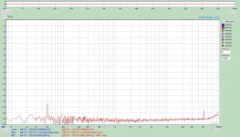
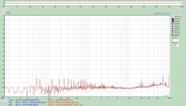
Attachments (y-scale in graphs includes the 60dB LNA):
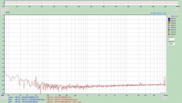
1. LNA input shorted
2. LNA shorted with 1k resistor. As the 1k resistor has a noise of 4nV/rtHz and the measured noise is about 10dB higher than baseline, the LNA should have below 2nV/rtHz noise.
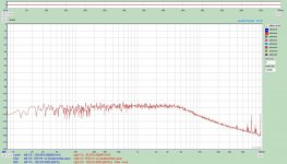
3. LM317 at 6V without bypass (Cadj)
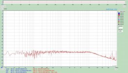
4. LM317 at 6V with 100uF bypass. Expected improvement.
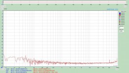
5. LM317 at 6V with denoiser. Still further improvement. However the spikes are bothersome.
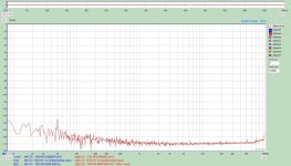
6. LT3042 at 5V. Excellent as according to the datasheet. Very close to the measurement limit.
7. LT3094 at -5V. Ditto.
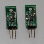
8. Pictures of my LT30xx boards. Layout follows datasheet recommendations.
Regarding the denoiser measurement I tried a couple of add-on denoisers I have built (one with SMD and one with TH). Results were the same. I'm not sure if the spikes are oscillations or just intrinsic to these denoisers. They may quite as well be due to the LM317 power supply I used in testing. However through oscilloscope no oscillations are visible and the overall noise level is clearly lower than with LM317 bypassed. I have also tested the improved dienoiser (with Sziklai). That clearly oscillated (as reported elsewhere on this thread) but even after suppressing the oscillations the results were more or less as with the basic denoiser (spikes included).
These results should make it clear why I have put the denoisers to rest and switched to LT30xx regulators 😀
I don't have APs or any other fancy equipment so these are not be taken as definitive results and the absolute numbers are probably meaningless. However the results may indicate ballpark relative merits of the DUTs.
My measurement setup was the following:
- MAudio ProFire 610 external soundcard (sampling at 192 kHz)
- AudioTester 3.0
- 60dB LNA
- Load was 200 Ohm + 100 uF parallel
- Regulator power supply was a small 12V lead acid battery
LNA was screened (diecast aluminum case within a stainless steel kettle). DUT and battery were in open air.
The DUTs were the following:
- Denoiser (single BJT) with LM317 at 6V.
- LT3042 at 5V
- LT3094 at -5V
Attachments (y-scale in graphs includes the 60dB LNA):
1. LNA input shorted
2. LNA shorted with 1k resistor. As the 1k resistor has a noise of 4nV/rtHz and the measured noise is about 10dB higher than baseline, the LNA should have below 2nV/rtHz noise.
3. LM317 at 6V without bypass (Cadj)
4. LM317 at 6V with 100uF bypass. Expected improvement.
5. LM317 at 6V with denoiser. Still further improvement. However the spikes are bothersome.
6. LT3042 at 5V. Excellent as according to the datasheet. Very close to the measurement limit.
7. LT3094 at -5V. Ditto.
8. Pictures of my LT30xx boards. Layout follows datasheet recommendations.
Regarding the denoiser measurement I tried a couple of add-on denoisers I have built (one with SMD and one with TH). Results were the same. I'm not sure if the spikes are oscillations or just intrinsic to these denoisers. They may quite as well be due to the LM317 power supply I used in testing. However through oscilloscope no oscillations are visible and the overall noise level is clearly lower than with LM317 bypassed. I have also tested the improved dienoiser (with Sziklai). That clearly oscillated (as reported elsewhere on this thread) but even after suppressing the oscillations the results were more or less as with the basic denoiser (spikes included).
These results should make it clear why I have put the denoisers to rest and switched to LT30xx regulators 😀
Attachments
-
 LNA_baseline.jpg62.9 KB · Views: 429
 -
 LNA+1k.jpg63.5 KB · Views: 393
 -
 LNA-LM317-nocap+6V.jpg63.9 KB · Views: 391
 -
 LNA-LM317-100u+6V.jpg63.8 KB · Views: 402
 -
 LNA-LM317-denoiser+6V.jpg65.5 KB · Views: 335
 -
 LNA-LT3042+5V.jpg63.2 KB · Views: 221
 -
 LNA-LT3094-5V.jpg63.3 KB · Views: 269
 -
 LT30xx.jpg955.2 KB · Views: 306
Ok, time for some measurements.
I don't have APs or any other fancy equipment so these are not be taken as definitive results and the absolute numbers are probably meaningless. However the results may indicate ballpark relative merits of the DUTs.
My measurement setup was the following:
- MAudio ProFire 610 external soundcard (sampling at 192 kHz)
- AudioTester 3.0
- 60dB LNA
- Load was 200 Ohm + 100 uF parallel
- Regulator power supply was a small 12V lead acid battery
LNA was screened (diecast aluminum case within a stainless steel kettle). DUT and battery were in open air.
The DUTs were the following:
- Denoiser (single BJT) with LM317 at 6V.
- LT3042 at 5V
- LT3094 at -5V
Attachments (y-scale in graphs includes the 60dB LNA):
1. LNA input shorted
2. LNA shorted with 1k resistor. As the 1k resistor has a noise of 4nV/rtHz and the measured noise is about 10dB higher than baseline, the LNA should have below 2nV/rtHz noise.
3. LM317 at 6V without bypass (Cadj)
4. LM317 at 6V with 100uF bypass. Expected improvement.
5. LM317 at 6V with denoiser. Still further improvement. However the spikes are bothersome.
6. LT3042 at 5V. Excellent as according to the datasheet. Very close to the measurement limit.
7. LT3094 at -5V. Ditto.
8. Pictures of my LT30xx boards. Layout follows datasheet recommendations.
Regarding the denoiser measurement I tried a couple of add-on denoisers I have built (one with SMD and one with TH). Results were the same. I'm not sure if the spikes are oscillations or just intrinsic to these denoisers. They may quite as well be due to the LM317 power supply I used in testing. However through oscilloscope no oscillations are visible and the overall noise level is clearly lower than with LM317 bypassed. I have also tested the improved dienoiser (with Sziklai). That clearly oscillated (as reported elsewhere on this thread) but even after suppressing the oscillations the results were more or less as with the basic denoiser (spikes included).
These results should make it clear why I have put the denoisers to rest and switched to LT30xx regulators 😀
Thank you very much
Can you help with some numbers from each measurents how many u/Volt noise do each measurents display?
Do you sell lt30xx boards?
Best regards
Last edited:
Ok, time for some measurements.
I don't have APs or any other fancy equipment so these are not be taken as definitive results and the absolute numbers are probably meaningless. However the results may indicate ballpark relative merits of the DUTs.
My measurement setup was the following:
- MAudio ProFire 610 external soundcard (sampling at 192 kHz)
- AudioTester 3.0
- 60dB LNA
- Load was 200 Ohm + 100 uF parallel
- Regulator power supply was a small 12V lead acid battery
LNA was screened (diecast aluminum case within a stainless steel kettle). DUT and battery were in open air.
The DUTs were the following:
- Denoiser (single BJT) with LM317 at 6V.
- LT3042 at 5V
- LT3094 at -5V
Attachments (y-scale in graphs includes the 60dB LNA):
1. LNA input shorted
2. LNA shorted with 1k resistor. As the 1k resistor has a noise of 4nV/rtHz and the measured noise is about 10dB higher than baseline, the LNA should have below 2nV/rtHz noise.
3. LM317 at 6V without bypass (Cadj)
4. LM317 at 6V with 100uF bypass. Expected improvement.
5. LM317 at 6V with denoiser. Still further improvement. However the spikes are bothersome.
6. LT3042 at 5V. Excellent as according to the datasheet. Very close to the measurement limit.
7. LT3094 at -5V. Ditto.
8. Pictures of my LT30xx boards. Layout follows datasheet recommendations.
Regarding the denoiser measurement I tried a couple of add-on denoisers I have built (one with SMD and one with TH). Results were the same. I'm not sure if the spikes are oscillations or just intrinsic to these denoisers. They may quite as well be due to the LM317 power supply I used in testing. However through oscilloscope no oscillations are visible and the overall noise level is clearly lower than with LM317 bypassed. I have also tested the improved dienoiser (with Sziklai). That clearly oscillated (as reported elsewhere on this thread) but even after suppressing the oscillations the results were more or less as with the basic denoiser (spikes included).
These results should make it clear why I have put the denoisers to rest and switched to LT30xx regulators 😀
Since layout for the denoisers matter can you please share with us the two regulators you tested? Pictures of them, and of the layout? It's really important.
There's been people making mistakes with these, in layout and part choice. Also you say they are add-ons, not full lm317 circuits? How did you install them?
Last edited:
That pretty much ends the discussion effectively. Thank you for your effort and your time.
No it doesn't at all.
So all is based on hearsay and no denoizer/nonoizer was built (yet)? It may sound old fashioned but I think it is wise to first test the layouts and then let people have to boards made.
I have stated many times that this is a DIY project mainly for peeps who want to make them and test them out, I have not recommended to make&install them in nice gear.
I also have no monetary incentive to push this. The smd version is for whoever wants to spend 2$ (without shipping) on 5 boards from jlcpcb and the likes. There's nothing irresponsible in this. Stop fearmongering please.
Can you help with some numbers from each measurents how many u/Volt noise do each measurents display?
Do you sell lt30xx boards?
I would not use these graphs to calculate total noise or noise densities as no bandpass filters were applied. I leave that to someone having more sophisticated equipment.
I was not planning on selling any boards. I just made these since I had some empty space on a JLPCB 10x10cm order 😀 Besides I don't think these types of add-on boards are a proper way to implement LT30xx regulators.
Since layout for the denoisers matter can you please share with us the two regulators you tested? Pictures of them, and of the layout? It's really important.
There's been people making mistakes with these, in layout and part choice. Also you say they are add-ons, not full lm317 circuits? How did you install them?
I'm not claiming that my denoiser layouts are perfect but I would much rather see measurements of other denoisers that have been presented in this thread. The smd version I tested was already displayed in D-Noizator: a magic active noise canceller to retrofit & upgrade any 317-based V.Reg.. The TH-version had similar 3-legged construction.
BTW are you now suggesting that denoiser layout is more critical than LT30xx layout 😀
For newer low voltage designs it actually makes more sense to use step down smps before multiple lt3042 or other similar LDO's , not even a simple lm317 or other classical series regulator for heat management.Noise wise, the sheer size of those denoisers is their own ennemy. I'd stay with the Technics denoiser mainly because it's good enough for as low as 5v , cheap and easy to manufacture while lt30xx smd chips ask for more resources...Ok, time for some measurements...........
These results should make it clear why I have put the denoisers to rest and switched to LT30xx regulators 😀
BTW are you now suggesting that denoiser layout is more critical than LT30xx layout 😀
Of course not, I am saying that the layout is important for both. I am not interested in the discussion of what layout is more critical, I am saying that it matters.
Also for sure being an add-on then it's really important to the overall picture to know in which circuit did you install the add-on? What else was in that circuit? Was the lm317 driving a load or was it idle? Other sources of noise in that circuit? How optimal is that circuit layout where you used the add-on etc etc.
Having the lt3042 regs on a nice board with a nice layout and using an add-on in an unknown lm317 circuit is hardly a fair comparison no?
Noise wise, the sheer size of those denoisers is their own ennemy.
Well LT3042 is a 200mA device while LM317 is a 1.5A device. This makes them useful for different applications.
LM317 comes in a sot-223 package as well, and is still a 1.5A device. You could make it compact if you wanted to. THT has also the advantage of taking the heat away from the board. These things have intersecting applications but they each have their own use where the other has no place.
LM317 + simple denoiser could be also be used to drop the bulk heat away from the pcb, and then follow with another smd reg of your choice to take out whatever is left, and also wouldn't keep that much heat in the board.
Last edited:
- Home
- Amplifiers
- Power Supplies
- D-Noizator: a magic active noise canceller to retrofit & upgrade any 317-based VReg