Hello optimationman,
How is it going with your project with / without denoiser?
Did you replace a lm317/337 with a super regulator and made listening test?
Best regards
How is it going with your project with / without denoiser?
Did you replace a lm317/337 with a super regulator and made listening test?
Best regards
I installed the denoiser for the preamp 317/337 set with fine results after adding the 33ohm "stability" resistor. With this encouraging result, I then added a denoiser(with added 33ohm resistor) to the overall 317/337 regulator set. Again, this resulted in some type of problem I haven't resolved at the moment. Somehow back to back denoisers I have built don't compliment the operation/sound of my unit. Still scratching on this issue. But the single denoiser application is well worth the effort.
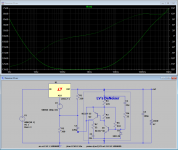
Forum member asked by PM for parts values suitable for 3,3V output. Here is BOM list with optimal values according to the LTSpice simulation. Predicted PSRR is around 130 dB. Using RH117H model, yields over 140 dB, but I prefer different LM317 model.
BOM is for schematics at:
D-Noizator: a magic active noise canceller to retrofit & upgrade any 317-based V.Reg.
BOM is for schematics at:
D-Noizator: a magic active noise canceller to retrofit & upgrade any 317-based V.Reg.
Attachments
Can LM350 or LM338 be used for higher current applications (assuming to have adequate heat sink)?
Last edited:
I am looking into a low-current (and therefore very compact) PSU board with for example AMS1117 type regulators so I can go full SMD on a few square cm's.
Besides the common 3.3 and 5.0 fixed output they also have an adjustable version.
Does anybody know how comparable AMS1117 (adj) is to LM317 internally and behaviour using a denoiser ?
Or should I better look at the LM317 in TO-92 ?
Besides the common 3.3 and 5.0 fixed output they also have an adjustable version.
Does anybody know how comparable AMS1117 (adj) is to LM317 internally and behaviour using a denoiser ?
Or should I better look at the LM317 in TO-92 ?
Last edited:
There is a fair chance it will work as intended. Quick check with LTspice and LT1117 regulator, which is very similar to the AMS1117, gives the same result as with LM317. However, simplified LTspice simulation is not a warranty that there could be no surprises.
You can use LM317M in SOT223 package if you want to be sure. I would check with LT1117 on the prototype board first.
You can use LM317M in SOT223 package if you want to be sure. I would check with LT1117 on the prototype board first.
The LM317M ... I forgot about that one but it is exactly what I need 
I better avoid AMS1117 to be safe ...
I better avoid AMS1117 to be safe ...
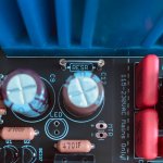
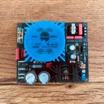
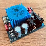
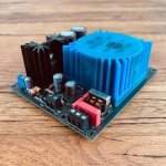
Here is the latest revision of my single positive rail board built up for 24V:


I added some primary pads to make my PCB compatible with 110V mains.

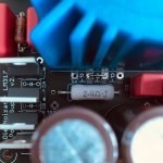
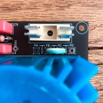
This revision also include the RESR resistor for tweaking the output impedance if required (although default is to jumper with Panasonic FC or Nichicon UPW 100uF 63v). The picture below socketed for easy swapping:

JUMPERS PRIMARY:
110V connect PA to PB and PC to PD
240V connect PB to PC only

JUMPERS SECONDARY:
Parallel connect SA to SB and SC to SD
Series connect SB to SC only

Next steps: I also received some excellent feedback from JP which I will try to implement in the next revision. I'll throw this into a scope to test for oscillations, but it's stable on DMM.
Schematic / Gerbers / BOM / Voltages attached.
I also have some spare boards available at fabrication cost.
I added some primary pads to make my PCB compatible with 110V mains.
This revision also include the RESR resistor for tweaking the output impedance if required (although default is to jumper with Panasonic FC or Nichicon UPW 100uF 63v). The picture below socketed for easy swapping:
JUMPERS PRIMARY:
110V connect PA to PB and PC to PD
240V connect PB to PC only
JUMPERS SECONDARY:
Parallel connect SA to SB and SC to SD
Series connect SB to SC only
Next steps: I also received some excellent feedback from JP which I will try to implement in the next revision. I'll throw this into a scope to test for oscillations, but it's stable on DMM.
Schematic / Gerbers / BOM / Voltages attached.
I also have some spare boards available at fabrication cost.
Attachments
-
 Voltages.gif26.5 KB · Views: 424
 -
Mouser BOM 5-24V.pdf47.4 KB · Views: 337
-
AC-PSU-v2_2020-07-23.zip143.5 KB · Views: 302
-
 IMG_8022.jpg282.4 KB · Views: 341
 -
 IMG_8021.jpg411.8 KB · Views: 249
 -
 IMG_8020.jpg541.5 KB · Views: 286
 -
 IMG_8009.jpg738 KB · Views: 314
 -
 IMG_8010.jpg618.3 KB · Views: 293
 -
 IMG_8011.jpg791 KB · Views: 317
 -
Schematic.pdf89.4 KB · Views: 645
Last edited:
Good idea to face the TO-220s all in the same direction, making it extremely difficult for the conductive mounting tabs to short together. But nothing is foolproof because fools are so ingenious.
Excellent job, nice and compact. I’m sure it will be useful to many forum members. Now, if you would provide negative rail version as well, that would be perfect 😀
Good idea to face the TO-220s all in the same direction, making it extremely difficult for the conductive mounting tabs to short together. But nothing is foolproof because fools are so ingenious.
Good point, will have a look for next rev!
Now, if you would provide negative rail version as well, that would be perfect
A D-Noizator PCB that provides bipolar outputs (±XX volts, adjustable) is linked in post #841 of this thread. Free Gerber download.
Just grabbed a couple of Andy's boards...(iamwhoiam).
Is there an alternative to the Murata inductor. EOL as far as I can from a few sources.
Thanks in advance. Look forward to building these up.
Is there an alternative to the Murata inductor. EOL as far as I can from a few sources.
Thanks in advance. Look forward to building these up.
Just grabbed a couple of Andy's boards...(iamwhoiam).
Is there an alternative to the Murata inductor. EOL as far as I can from a few sources.
Thanks in advance. Look forward to building these up.
They're a standard common mode choke with 13x10mm pitch and outer dimension of 18x15mm
Quite a few Murata ones on eBay.. Keyword search "murata pla10". The one I used above:
Murata PLA10AN4330R3R2B Cmc Filter 43mH 0.3A | eBay
The higher the value the stronger the filtering effect.
10mH-43mH and above should suffice. What voltage / amps are you thinking of configuring?
Hope that's helpful!
Last edited:
Thats great thanks. Not quite sure where they will be implemented yet! I'll devise a project for them I'm sure!
They're a standard common mode choke with 13x10mm pitch and outer dimension of 18x15mm
Quite a few Murata ones on eBay.. Keyword search "murata pla10". The one I used above:
Murata PLA10AN4330R3R2B Cmc Filter 43mH 0.3A | eBay
The higher the value the stronger the filtering effect.
10mH-43mH and above should suffice. What voltage / amps are you thinking of configuring?
Hope that's helpful!
Thats great thanks. Not quite sure where they will be implemented yet! I'll devise a project for them I'm sure!
I just had a quick browse on Mouser.
KEMET SU10VFC fits very nicely here. Values 14, 25, 37mH all in stock and cheaper than eBay Muratas.
https://www.mouser.co.uk/KEMET/Common-Mode-Chokes-Filters/SU10VFC-Series/_/N-1z0znw3ZwpdnZ1y8dkgi
Attachments
Last edited:
Thats great info thankyou. I'm currently collating a Mouser order so I'll go with one of those.
I have been following with interest Abraxilto's reference tda8932 amplifier project in which he uses lm317s to power 2 of the rails of the chip. He cites that the datasheet RC filter on those rails isn't optimal and his use of regs there makes for a good improvement. So i am wondering what these de noisers could do for the same job.
I have been following with interest Abraxilto's reference tda8932 amplifier project in which he uses lm317s to power 2 of the rails of the chip. He cites that the datasheet RC filter on those rails isn't optimal and his use of regs there makes for a good improvement. So i am wondering what these de noisers could do for the same job.
Schematic / Gerbers / BOM / Voltages attached.
I also have some spare boards available at fabrication cost.
I have just checked, and the version you have done it's the Dienoiser.
Have you experienced any oscillations problems like others have with this version?
Have you had the chance to make listening comparisons with other regulators applied on the same audio circuit?
Thats great info thankyou. I'm currently collating a Mouser order so I'll go with one of those.
I have been following with interest Abraxilto's reference tda8932 amplifier project in which he uses lm317s to power 2 of the rails of the chip. He cites that the datasheet RC filter on those rails isn't optimal and his use of regs there makes for a good improvement. So i am wondering what these de noisers could do for the same job.
Is this the amplifier you talk about?
https://www.nxp.com/docs/en/data-sheet/TDA8932B.pdf?
What would you power with the Denoiser or Dienoiser?
This is Abraxiltos implementation of the tda8932 using lm317s for 2 of the supply rails to the chip.
Transformer input TDA8932 mono amp
I think the regs power pins 8, 20, and 29
Transformer input TDA8932 mono amp
I think the regs power pins 8, 20, and 29
- Home
- Amplifiers
- Power Supplies
- D-Noizator: a magic active noise canceller to retrofit & upgrade any 317-based VReg