Low noise BJT.
A quick goo.... and saw this!
https://www.beis.de/Elektronik/LNPreAmp/5xTransistorNoise.gif
A quick goo.... and saw this!
https://www.beis.de/Elektronik/LNPreAmp/5xTransistorNoise.gif
Same basic circuit as for the standard denoizator, but with the resistors value around the transistor amplifier adapted as a function of the (high) output voltage.Morning Elvee
Your D-Noizator fix for the Maida Regulator Please.
Some caveats though:
As the input is bootstrapped to the output, it will change the loop characteristics, which could be problematic: the denoizator is supposed to be used with plain-vanilla, non-augmented circuits.
You are free to try it of course, but it might not be possible to stabilize it.
Another problem is the dissipation: to be effective, the amplifier needs to run at a few mA, typically 5.
As you will calculate the amplifier to keep the Vce under 10V, the collector load will dissipate a non-negligible amount of power: >1W for 250V for example.
The capacitors will need to withstand ~all of the output voltage: imagine the size of a 220µF/250V cap.
In principle, the nonoiser can use smaller caps, but I am practically certain that it will be impossible to stabilize with a Maida
THANKS, Elvee!! I can't wait to try it! How much reduction in noise voltage would you expect? RC4194 datasheet quotes 250µVolts noise for 15 volts out.In fact, I did make a silly mistake. Here is the correct version (hopefully).
I am considering adding the DeNoiser add-on to my pre-amplifier power section.
It has multiple LM317/337 combo's with one high voltage with +/- 52 Vdc:
(from the service manual)
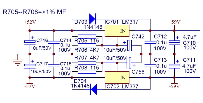
The BC337 is limited to 45 Vdc so what alternative higher voltage rating transistor would be advised and do I need to change some resistors R4/R5/R6 to other values too ?
Does the control benefit using a higer value reference resistor R1 (220 vs 115 ohm) which would set R2 as 9 kohm to get 52V.
It has multiple LM317/337 combo's with one high voltage with +/- 52 Vdc:
(from the service manual)
The BC337 is limited to 45 Vdc so what alternative higher voltage rating transistor would be advised and do I need to change some resistors R4/R5/R6 to other values too ?
Does the control benefit using a higer value reference resistor R1 (220 vs 115 ohm) which would set R2 as 9 kohm to get 52V.
Enthusiasm effectively curbed. I think there are mistakes in your adaptation to the RC4194. The positive side seems all wrong to me---using a BC327 (same as the negative side) and feeding the + output signal to the emitter seems wrong---it's fed (via a 22uF DC blocker) to the base of a BC337 in the original LM317 version. What's happening here?If it actually works, you can expect 40db or more, because the impedances are more favorable than in a 317. But don't get too enthustiastic for now: you might never be able to get it stable
Looks fine to meSo far I understand transistors ... i think ;-)
??
G'day Guys,
If one was trying to maximise the efficacy of the CRC filter before the denoiser reg, then how low would one want to set the corner frequency?
I intend to use an LM317 denoiser for a tube preamp heater supply.
2x 6SN7 in series for 12vdc at max 650mA.
With this sort of current draw, using a 10R resistor for the RC filter results in unacceptably high voltage drops of something in the order of 6v which would not leave me with enough voltage drop left for sufficient regulation.
Thus, I am trying to balance capacitor size to resistor value to come up with something more like a 1v drop across the resistor. This seems to end up somewhere in the margin of 1.5R but now the capacitor size is going up which means cost and pcb real estate.
Values such as: 1.5R with 4700uF yield a corner of 22.5Hz. Is this low enough?
Do I need to target more like the 7.2Hz yielded by 10R with 2200uF?
With a filter having 6dB/octave, you need a corner frequency as low as practicable, meaning either a large cap, or a large resistive drop or a mix of both.
Not very attractive, and a waste IMHO for a heater, even in preamp applications
The most euphemistic description of a brain damaged idea I have ever seen.
Gerhard
Not enough for heaters.Precede the LM317+denoiser with an LDO. 1 ampere maximum.
- Home
- Amplifiers
- Power Supplies
- D-Noizator: a magic active noise canceller to retrofit & upgrade any 317-based V.Reg.