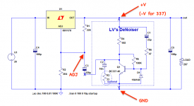
The important thing is to connect the denoiser as close as possible to the output. This means the input cap and GND (emitter).Some time ago I did mention here a grounding arrangement for some parts in any chip regulators, that was suggested in TNT-Audio as something that could affect impedance.
Simple Voltage Regulators Part 2: Output Impedance
Got not feedback about it.
As I am working on a easier way to build the Denoise and Diego's version, I'm thinking of building that simple mod into the board.
It would demand desoldering one more resistor from the original regulator, when connecting the pcbs, but with potential improvements, I think.
That improvement is shown in TNT's article, thought I doubt it will show in any simulation.
Comments are welcome.
Moving the DC voltage setting resistor to the same point could improve very marginally the DC load regulation if the original layout is lousy, but on the + side, the problem is similar and there is nothing you can do: the resistor has to be connected as close as possible to the regulator, not the load, which will generally be the case
@Indaco
I mentioned increasing L cause i'm building up CLCLC and with using 4700uF caps, coil 20mH fc is around 16Hz. I bought this cores B64290L0647X038 EPCOS / TDK | Mouser Croatia they have pretty high inductance so you get 20mH with around 30-40 turns of wire,at least i calculated that with data from datasheet.Still needs to be verified in practice.
Khadgar, I took a look on the datasheet...if you mean the T38 toroid, then yes the number of turns is correct as you say since for 20 mH, N = 1000√L(mH)/Al = 39 turns.
I imagine with a couple of them and the capacitors the board starts to be bulky. You need to consider if the juice worth the squeeze
Phase linearity?
It seems Elvee dealt with noise issues of notorious LM317/LM337 based regulators. But what about other aspects like phase and impedance linearity in audio band?
Jbau experimented with phase and impedance linearity issues of these regulators and contrıbuted some interesting results (click here). His final circuit schematic is here (a few posts below). He concluded a 20 miliohm buffer resistor and a 560uF capacitor at output.
If we can manage to bring together the both worlds, low noise and linearity, we could have an ideal analog power supply with widely available diy friendly common parts.
What do you think?
Phase linearity is plain non-sense in this context: all you need to know is the complex impedance, it includes magnitude and phase information.
The most important parameter is the magnitude: in fact, if it is small enough, the phase is not going to matter.
By nature, because it is a servo-system, a voltage regulator has an inductive behavior.
When this inductance is paralleled with a capacitor (output bypass for example), it will resonate at some frequency resulting in an impedance peak.
So, phase matters in a way, but the result is seen in the magnitude.
If you try to make the phase=0 for all the frequency range, you will lose sight of other important parameters.
Hi Dotneck,
What 33R resistor is that you're using in series with 10n?
I don't have any resistor like that on my schematic.
The 33R gives a pleasant little boost to the phase margin of the negative feedback control system. Elvee described it a few months ago. If you're experimenting with the circuit in software simulation, ".STEP" that resistor's value from 0.33R to 33R (2 decades), at 6 points per decade. Aha! There it is.
Start searching beginning with post #400 or thereabouts, and scan through the messages, 50 messages per screen, looking at the attachments. You'll find it quickly enough.
_
Start searching beginning with post #400 or thereabouts, and scan through the messages, 50 messages per screen, looking at the attachments. You'll find it quickly enough.
_
Exactly, but it is mostly suited to other, more "nervous" regulators.
For a regular 317, making it 0 is probably preferable.
The 337 is a shade less placid and can benefit from it.
For most other types, I didn't make actual, physical tests, and I cannot give definitive advices
For a regular 317, making it 0 is probably preferable.
The 337 is a shade less placid and can benefit from it.
For most other types, I didn't make actual, physical tests, and I cannot give definitive advices
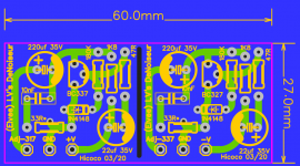
Hello !
Not bad...but no place left for heatsink
Could it be possible to mount a heatsink long as the pcb and attach both regulators on?
Tested OK.
I take the opportunity to rectify one or two mistakes:
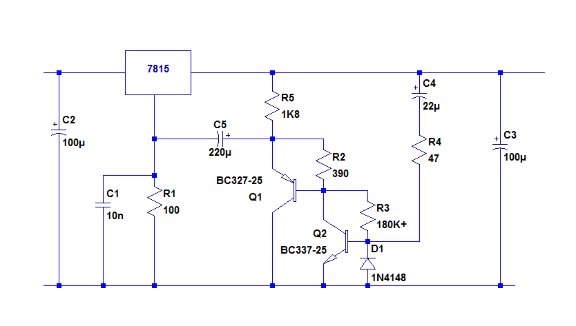
C5 needs to be reversed
R3 should be returned to the collector of Q2 to increase the Vce
R3 could be larger than 180K for the same reason
A compensation cap is required, as for other versions; a few nF is sufficient. 10nF is safe.
Is this 7815 version suitable for fixed 117/1117 regs? Or the regular D(i)enoiser/Nonoiser ones with isolated regulator ground pins (10n||100R)?
Last edited:
Heatsink for what? Hicoko made just plugin board so you can connect it to existing LM317 regulator.
 or/and 337
The 7815 circuit could work with the 317, but it is of course preferable to use the dedicated die- or de-noiser version (unless rowing upstream is your thing)Is this 7815 version suitable for fixed 117/1117 regs? Or the regular D(i)enoiser/Nonoiser ones with isolated regulator ground pins (10n||100R)?
- Home
- Amplifiers
- Power Supplies
- D-Noizator: a magic active noise canceller to retrofit & upgrade any 317-based V.Reg.