Not enough for heaters.
I intend to use an LM317 denoiser for a tube preamp heater supply.
2x 6SN7 in series for 12vdc at max 650mA.
1000 milliamperes looks okay to me
With a filter having 6dB/octave, you need a corner frequency as low as practicable, meaning either a large cap, or a large resistive drop or a mix of both.
Not very attractive, and a waste IMHO for a heater, even in preamp applications
The most euphemistic description of a brain damaged idea I have ever seen.
Gerhard
Let us assume for a moment that I am the worst kind of brain damaged noob imaginable (the kind that wants to 'upgrade' everything with $100 film caps for example).
I can see 2 arguments here:
a) This is a costly and inefficient way to go about maximising performance.
This rapidly becomes evident when considering the cost of the 10000uF caps which become necessary.
b) I am aspiring to a level of performance unnecessary for a heater supply.
Where is the line here?
Is there any point using a denoiser at all for a heater supply or would a simple rig with an LT1086 be more than sufficient?
Precede the LM317+denoiser with an LDO. Remove as much yecch and crudd and mains-ripple as you can, so the denoiser has less work to do. This one only needs 0.5V from in to out, only costs USD 1.96, and is rated for 1 ampere maximum.
That is an interesting suggestion.
I've been staring at RC filter curves. It seems that even when set very aggressively, an RCRC filter can offer at most something in the order of -30db at 50-60Hz. Whereas from the spec sheet the BD00C0AW seems to offer something like 55db.
This also looks to be cheaper than the bulk cap/resistor approach as above.
One reason I am choosing a 12v heater here is so that I can lower the current demands and keep LM317 dissipation low.Not enough for heaters.
The other reason is due to their being a lack of power transformers with both HV and something like a 10v secondary for regulating down to 6.3v. They all seem to be 6.3v which doesn't offer sufficient headroom for regulation etc.
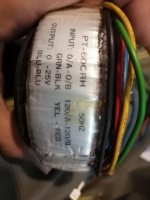
This is the most likely candidate right now.
https://www.ebay.com/itm/30VA-HIFI-copper-R-core-transformer-Output-0-220V-0-14V-for-tube-preamp-L5-3/123117978137?hash=item1caa674219:g:5QIAAOSwgFJa6dl7
The other advantage is that I can then install a dip switch to select between series and parallel so that I can use 12SN7 tubes should I desire in the future.
I do have to ask the question as to the brief over voltage that occurs during startup of a denoiser:
Lets say I regulate for 6v. Would the brief time the heater is exposed to 7v or so, have any effect on tube life?
As I understand, tubes don't mind a bit of under voltage on the heaters but do not like over voltage.
Since this is perhaps skirting around the edge of the denoiser discussion. Let me know If I am getting too far off topic here and I will shift to a new thread.
The 1086 is a decent regulator, and should eliminate all the magnetic induction and electrostatic coupling issues completely.Is there any point using a denoiser at all for a heater supply or would a simple rig with an LT1086 be more than sufficient?
It also has a lower dropout than the 317.
DC feeding of heaters has been discussed on numerous occasions in the tube section. You can probably find lots of useful information there
The 1086 is a decent regulator, and should eliminate all the magnetic induction and electrostatic coupling issues completely.
It also has a lower dropout than the 317.
Assuming the lower dropout is not a necessity which it my case it is not. A denoiser costs something like NZ$5 compared to NZ$10.5 for an LT1086 from Mouser. The denoiser seems to offer lower cost than the LT1086 and higher performance.
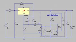
If I was to take Mark Johnson's suggestion of a regulator before the denoiser for additional filtering, and use a reg I have on hand such as the LD1086 (also, the datasheet on that BD00C0AW doesn't clearly explain to me what to do with the ctrl pin no matter how much I stare), I might come up with something like this:

Is there any reason why this wouldn't work or is particularly stupid?
This is parts from the bin and whilst perhaps unnecessary, it might just satisfy my inner compulsions at a fraction of the cost compared to all of them shiny and expensive parts that litter the internet.
So far i think this is a bit overkill. I made simple benchtop PSU with denoiser, 2x2200uF bulk elkos before LM317 without any RC filtration. When i attach EL84 on it i get around 250uV ripple.Cause my PSU is all in box i can't measure ripple of bulk elkos so i know what's exact ripple reduction of my denoiser. People build MM phono stages with simple RCRCRC filtration without huge capacitors and results are completely noiseless phono stage. I would suggest that you add maybe some series BJT to increase available current and remove some stress from LM317.
edit:
But ofc i'm all up for experimenting but thing is can you measure results? Because i'm pretty sure you won't be able to hear difference. Amount of ripple PSU needs to have so you can hear it's influence in output signal probably needs to be quite big so every decent variation of LM317/78xx,LDO's are good enough to supply heater of tube.
Last edited:
If the BD00C0AW voltage regulator IC is too complicated/confusing, and if the LT1086 is too expensive at NZD 10.50 ...
Then perhaps a simple capacitance multiplier might be a cheap and simplistic compromise, to serve as a pre-filter before a deNoiser. A well designed C.M. will reduce the mains ripple by 20-45 dB and improve PSRR throughout the audio band. If you decide to build it for OTHER tube heaters which require quite a lot more than 1 ampere, that's quite easy to achieve. And if you decide to build it for 650mA, that's a little easier. Depending on the design style used, a capacitance multiplier can achieve an input-to-output voltage less than 1 volt, which appears to be quite acceptable since that's the datasheet spec of the LT1086. If you dare to employ depletion mode MOSFETs in the C.M., even less.
Then perhaps a simple capacitance multiplier might be a cheap and simplistic compromise, to serve as a pre-filter before a deNoiser. A well designed C.M. will reduce the mains ripple by 20-45 dB and improve PSRR throughout the audio band. If you decide to build it for OTHER tube heaters which require quite a lot more than 1 ampere, that's quite easy to achieve. And if you decide to build it for 650mA, that's a little easier. Depending on the design style used, a capacitance multiplier can achieve an input-to-output voltage less than 1 volt, which appears to be quite acceptable since that's the datasheet spec of the LT1086. If you dare to employ depletion mode MOSFETs in the C.M., even less.
It will definitely work, it is not stupid, but it depends on what you mean at "work". There are several ways through which noise goes inside a tube amplifier, and heater noise (differential type noise) is only one of them. There is common mode noise too. So I want to warn you and to repeat Elvee quote:Is there any reason why this wouldn't work or is particularly stupid?
DC feeding of heaters has been discussed on numerous occasions in the tube section. You can probably find lots of useful information there
Last edited:
Let us assume for a moment that I am the worst kind of brain damaged noob imaginable (the kind that wants to 'upgrade' everything with $100 film caps for example).
I can see 2 arguments here:
a) This is a costly and inefficient way to go about maximising performance.
This rapidly becomes evident when considering the cost of the 10000uF caps which become necessary.
b) I am aspiring to a level of performance unnecessary for a heater supply.
Where is the line here?
Is there any point using a denoiser at all for a heater supply or would a simple rig with an LT1086 be more than sufficient?
That is an interesting suggestion.
I've been staring at RC filter curves. It seems that even when set very aggressively, an RCRC filter can offer at most something in the order of -30db at 50-60Hz. Whereas from the spec sheet the BD00C0AW seems to offer something like 55db.
This also looks to be cheaper than the bulk cap/resistor approach as above.
One reason I am choosing a 12v heater here is so that I can lower the current demands and keep LM317 dissipation low.
The other reason is due to their being a lack of power transformers with both HV and something like a 10v secondary for regulating down to 6.3v. They all seem to be 6.3v which doesn't offer sufficient headroom for regulation etc.
I do have to ask the question as to the brief over voltage that occurs during startup of a denoiser:
Lets say I regulate for 6v. Would the brief time the heater is exposed to 7v or so, have any effect on tube life?
As I understand, tubes don't mind a bit of under voltage on the heaters but do not like over voltage.
I wrote that the idea is brain dead, not you.
This is not a way to maximize performance. The added benefit is zero or even
negative when the complication is considered. Most tubes are designed to be
heated by 6.3V AC, and it IS possible to do it in a way that the hum does not
hurt. Rectifying and some passive filtering should be more than enough.
Heater and cathode are insulated. I would not bet my life on glowing red
ceramic, but to a pretty great degree there is no connection.
Short over-voltage transients do no harm as long as they are not so bad
as to melt the heater wire. Constant underheating can be bad for the
tube life as it can impair the ability to emit electrons in the long run.
Costly transmitting tubes require some preheating before plate and screen
voltage may be applied - to inhibit current from the semi heated cathode.
regards, Gerhard
Why not in your particular case: if it is cheaper, has higher performance and the dropout and added complexity is tolerableAssuming the lower dropout is not a necessity which it my case it is not. A denoiser costs something like NZ$5 compared to NZ$10.5 for an LT1086 from Mouser. The denoiser seems to offer lower cost than the LT1086 and higher performance.
Ctrl is the ON/OFF switch: H to activate the output. it is TTL compatible, but you can just tie it to any convenient positive sourceIf I was to take Mark Johnson's suggestion of a regulator before the denoiser for additional filtering, and use a reg I have on hand such as the LD1086 (also, the datasheet on that BD00C0AW doesn't clearly explain to me what to do with the ctrl pin no matter how much I stare), I might come up with something like this:
It should work, even if the complexity is unnecessaryView attachment 841892
Is there any reason why this wouldn't work or is particularly stupid?
This is parts from the bin and whilst perhaps unnecessary, it might just satisfy my inner compulsions at a fraction of the cost compared to all of them shiny and expensive parts that litter the internet.
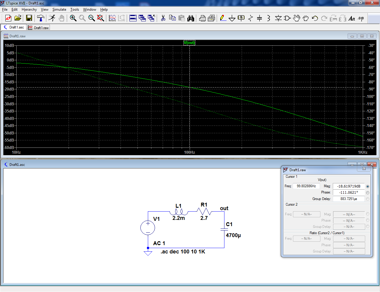
I have a question to ask if I want to try a low pass filter before the regulator. In fact, the use of an appropriate LC filter had previously been mentioned for better ripple (noise) rejection. So why not maybe an RLC (series)?
With the [FONT=MathJax_Math] ζ[/FONT] > 1 (overdamped) there would be no risk of having the peak that falls in the 10^2 range, producing a bad ripple effect. R also should be low for not too much voltage drop. So I calculated something like this:
R= 2.7 ohm, L= 2.2 mH and C= 4700 uF
With these values [FONT=MathJax_Math]ζ[/FONT] = 2, ωo = 300 Hz and fc = 50 Hz. It seems to me a good point, how about it?
Well, if i would go this way and sometimes i do(with RC filtering for tube projects) i try calculate RLC parts so fc is under 20Hz to put it out of audio range. Yes i know that for low voltage applications is a bit tricky and costly and maybe not needed for denoiser but what the hell, if you think then think big. 
It gives you a rejection of a little under 20dB at 100Hz:I have a question to ask if I want to try a low pass filter before the regulator. In fact, the use of an appropriate LC filter had previously been mentioned for better ripple (noise) rejection. So why not maybe an RLC (series)?
With the [FONT=MathJax_Math] ζ[/FONT] > 1 (overdamped) there would be no risk of having the peak that falls in the 10^2 range, producing a bad ripple effect. R also should be low for not too much voltage drop. So I calculated something like this:
R= 2.7 ohm, L= 2.2 mH and C= 4700 uF
With these values [FONT=MathJax_Math]ζ[/FONT] = 2, ωo = 300 Hz and fc = 50 Hz. It seems to me a good point, how about it?
If you really need that little boost, why not?
Attachments
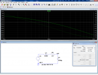
It gives you a rejection of a little under 20dB at 100Hz:
If you really need that little boost, why not?
Thanks for simulation Elvee, as Khadgar suggests maybe I could go down for fc increasing L. At this point it would become not so cheap though, especially with rather high I(max) on L
Smaller TH
YEAH!! Thanks!! Post the gerber files and I'll be the guinea [pig]. I volunteer to be the first one to order some boards and try them out
Hicoco---any progress on the test of the DeNoiser add-on layout? I'm still willing to try it out if you don't have the time (at present I have LOTS of that!!)Perhaps...
I will order PCB and test it before any post
On power up, the regulators see a 59V transient between Vin and ADJ.
I would not bet that they tolerate that forever.
Would they be protected if you change D703/D704 to 35v zeners?
I have seen high voltage regulators, one used in a The Audio Amateur Magazine article to power low current stages on a Hafler DH200 power amp, they added that zener for protection.
How protected would the whole regulator be?
@Indaco
I mentioned increasing L cause i'm building up CLCLC and with using 4700uF caps, coil 20mH fc is around 16Hz. I bought this cores B64290L0647X038 EPCOS / TDK | Mouser Croatia they have pretty high inductance so you get 20mH with around 30-40 turns of wire,at least i calculated that with data from datasheet.Still needs to be verified in practice.
I mentioned increasing L cause i'm building up CLCLC and with using 4700uF caps, coil 20mH fc is around 16Hz. I bought this cores B64290L0647X038 EPCOS / TDK | Mouser Croatia they have pretty high inductance so you get 20mH with around 30-40 turns of wire,at least i calculated that with data from datasheet.Still needs to be verified in practice.
Some time ago I did mention here a grounding arrangement for some parts in any chip regulators, that was suggested in TNT-Audio as something that could affect impedance.
Simple Voltage Regulators Part 2: Output Impedance
Got not feedback about it.
As I am working on a easier way to build the Denoise and Diego's version, I'm thinking of building that simple mod into the board.
It would demand desoldering one more resistor from the original regulator, when connecting the pcbs, but with potential improvements, I think.
That improvement is shown in TNT's article, thought I doubt it will show in any simulation.
Comments are welcome.
Attachments
Not really: you need to use a 317HV or control the supply's rate of rise.Would they be protected if you change D703/D704 to 35v zeners?
Using a floating regulator in a situation where the absolute voltages exceed the abs max ratings generally ends in disaster, even if under normal conditions the relative voltages look safe.I have seen high voltage regulators, one used in a The Audio Amateur Magazine article to power low current stages on a Hafler DH200 power amp, they added that zener for protection.
How protected would the whole regulator be?
There are so many possible situations of startup, shutdown or abnormal conditions that one will eventually be fatal.
With 35 turns, and a Al of 13100, you could arrive at ~16mH, but being a toroid it is ungapped.@Indaco
I mentioned increasing L cause i'm building up CLCLC and with using 4700uF caps, coil 20mH fc is around 16Hz. I bought this cores B64290L0647X038 EPCOS / TDK | Mouser Croatia they have pretty high inductance so you get 20mH with around 30-40 turns of wire,at least i calculated that with data from datasheet.Still needs to be verified in practice.
If you tolerate an induction of 300mT, which is barely reasonable for this material, the max DC current will be 35*0.3*77e-6/0.016=50.5mA
Maybe it's OK for you?
- Home
- Amplifiers
- Power Supplies
- D-Noizator: a magic active noise canceller to retrofit & upgrade any 317-based V.Reg.