Out of curiosity, what is the expected difference in ripple rejection by using a 10,000µF-10R-10,000µF CRC filter as opposed to a single 22,000µF capacitor? (Using 22 instead of 20 because that's what is commonly available)
On what circuit?
I think Calmart showed a simulation earlier in the thread which shows the difference in noise between a CRC filter before the regulator and a single cap although no so large.
The idea here is to sacrifice a little bit of voltage through the resistor for the sake of pre filtering before the regulator.
I could also have used an inductor for a CLC supply however finding a suitable inductor is a bit more annoying than a nice simple CRC supply.
The idea here is to sacrifice a little bit of voltage through the resistor for the sake of pre filtering before the regulator.
I could also have used an inductor for a CLC supply however finding a suitable inductor is a bit more annoying than a nice simple CRC supply.
Last edited:
To be really effective at 100/120Hz, an inductor needs iron, not ferrite.
However, it is probably possible to find a 12mH ferrite inductor having a DC resistance of 10 ohm for an acceptable price: it will perform marginally better than a plain resistor (~+40%), but will greatly improve the HF rejection, in case it matters (I don't think so, but Carl does not seem to follow an objective, down to earth trajectory so it might appeal to him)
However, it is probably possible to find a 12mH ferrite inductor having a DC resistance of 10 ohm for an acceptable price: it will perform marginally better than a plain resistor (~+40%), but will greatly improve the HF rejection, in case it matters (I don't think so, but Carl does not seem to follow an objective, down to earth trajectory so it might appeal to him)
Well, a main reason to use an inductor instead of a resistor is to get similar ripple rejection without the voltage drop of a 10Ω resistor; so we need a DC resistance of less than 1Ω, I'd say. The other problem I see is getting an inductor that will handle a reasonable amount of current that will fit. The only 12mH inductor that I found that would handle 1 amp was >$7 and 1.5" diameter. If you know of a better alternative, I'd love to hear about it!!
To be really effective at 100/120Hz, an inductor needs iron, not ferrite.
However, it is probably possible to find a 12mH ferrite inductor having a DC resistance of 10 ohm for an acceptable price: it will perform marginally better than a plain resistor (~+40%), but will greatly improve the HF rejection, in case it matters (I don't think so, but Carl does not seem to follow an objective, down to earth trajectory so it might appeal to him)
You're wrong. I do follow an objective: to provide a regulator for the low current stage of an amplifier, which the manufacturer found important to have. And my objective stops there.
Not costing much is also very important, which the manufacturer also followed. Having expensive and bulky inductors is not in my plans, and that's why I also went back to the original CRC idea. Also found a way to make the filter capacitors smaller, by using a darlington on the CM.
Maybe the darlington is the only thing that is not essential, but, well, it's just four parts, costing $4 more?
The simulations were very useful to see what we could get, even from apparently simple circuits.
As I will be able to compare this power amp clone with the original, who knows, I may compare the original regulator with the slightly more elaborate one. And listen if it does affect things, audio-wise.
This is an '80s amplifier, and one that sounds awfully good. I'm not sure which was its PSRR.
But the reason for me still thinking a regulator being important on some parts of a power amp were measurements that showed how the output current demands, as it played music, affected the bias voltage, increasing THD every time it did.
Some amplifiers solve that with separate secondaries to feed the low current stages with a simple filter, some add another transformer and regulate that, some boost the sole transformer voltage going to low current stages and regulate that.
Such RC gives more than 50 times ripple rejection (about 63), or about 36 dB (for 50 Hz mains) itself. It depends on load value too. So 10R and 10000uF are great values.Out of curiosity, what is the expected difference in ripple rejection by using a 10,000µF-10R-10,000µF CRC filter as opposed to a single 22,000µF capacitor?
Single 22mF filter have 2.2 times smaler ripple then 10mF filter. So CRC with large enough R is much better then only large C: 63/2.2 = 29 times better (29 dB).
RC-filter calculation is easy (it isn't very accurate because of I neglect load impedance and rectifier with transformer ets impedance, but it is accurate "Enough for Australia"
10R is 10R.
10mF is 0.159R at 100 Hz (0.133R for 120Hz).
So, ripple rejection is 10R/0.159R = 62.9 times for 100 Hz (or 75.5 times for 120 Hz).
Last edited:
Yes, MUCH better ripple rejection!! Curious as to how you got your figures, though. I looked at the datasheet for a Nichicon cap (KW or FW) 10, 000µF, 50 volt and saw a tan δ of 0.30 (0.12 plus 9 x 0.02 for the added capacitance) @ 120 Hz. Using the formula ESR = DF / 2π x f x C, I calculate 0.04Ω. That, with a 10Ω resistor, would give a reduction of 48 db. WOW!! Can it really be that much better?
Last edited:
Ok, you are correct. The reactance of a 10, 000µF cap is 0.13Ω @ 120Hz. Vectorially adding the 0.13Ω reactance and the 0.04Ω ESR gives 0.136Ω. That makes it -37.4 db. Still, a lot!!Why you take into consideration only ESR? It's only a part of full impedance. I use reactive impedance for calculations. It is usually some larger then ESR, so we can don't take ESR into concideration (to make calcs easier).
Hi Elvee !!!
Thank you very much for your great contribution!!!.
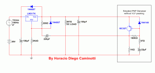
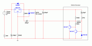
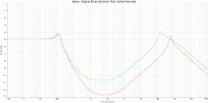
I add a modified option of your denoiser, which seems not to produce the peak at a very low frequency . I have not tested it in my workbench (only in simulations).
Best regards

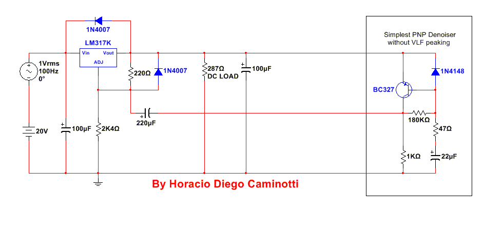
Thank you very much for your great contribution!!!.
I add a modified option of your denoiser, which seems not to produce the peak at a very low frequency
Best regards
Attachments
Last edited:
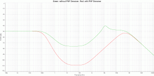
Simplest PNP Denoiser vs. traditional regulator configuration without PNP Denoiser:
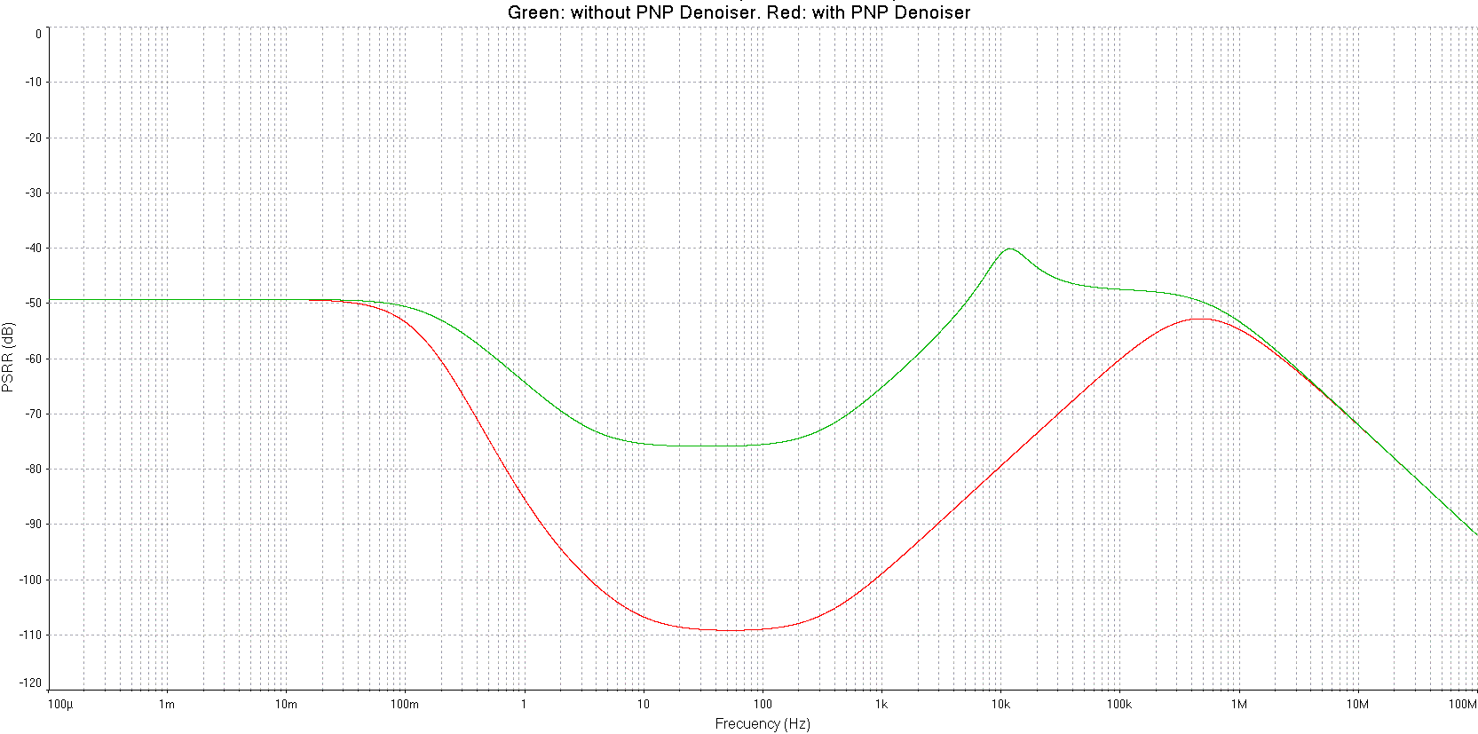
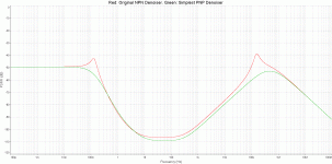
Original Elvee NPN Denoiser vs. Simplest PNP Denoiser:
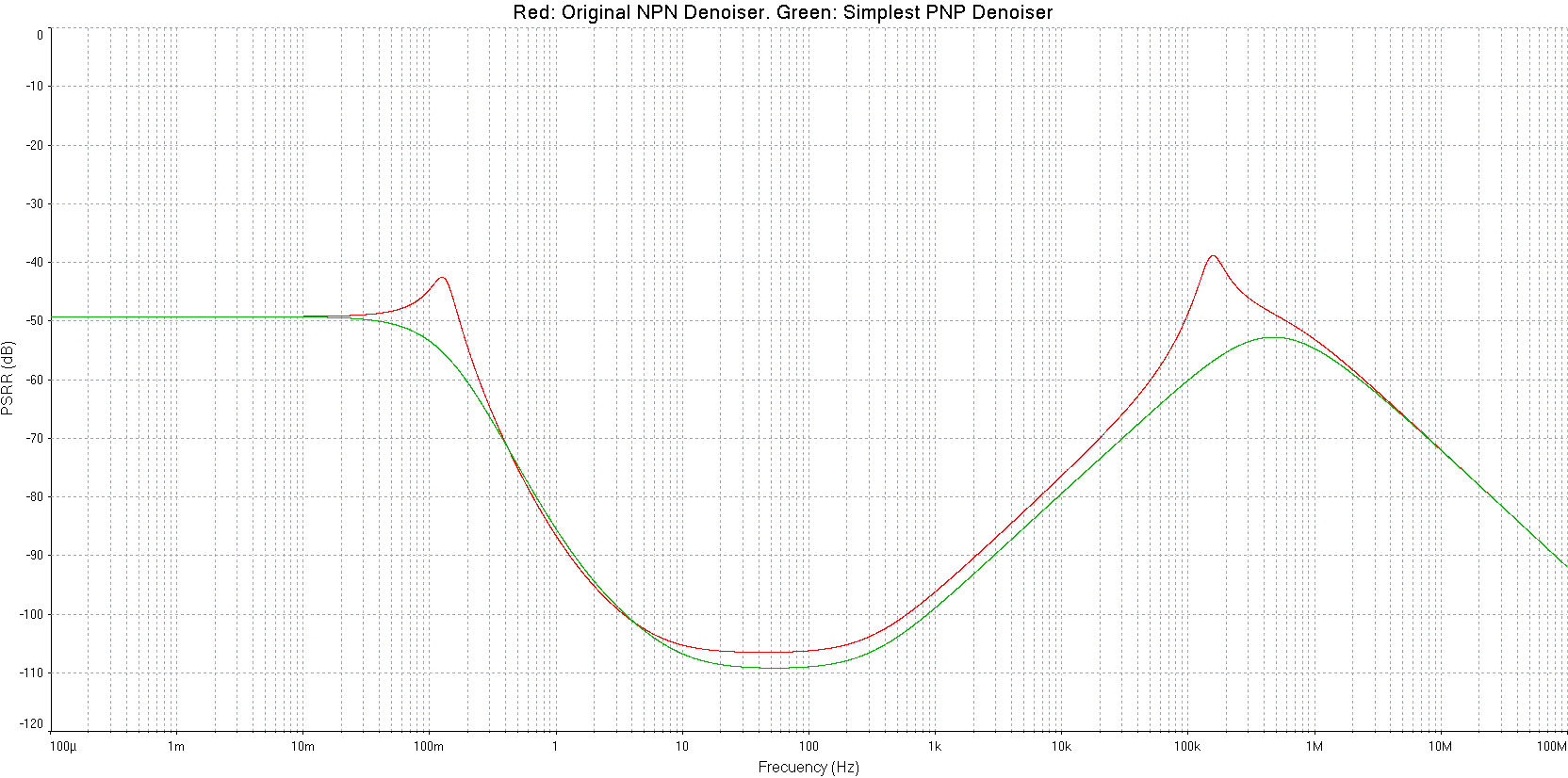
Original Elvee NPN Denoiser vs. Simplest PNP Denoiser:
Attachments
Last edited:
AC analysis does not care about the polarity of the feedback, or even the functionality of the circuit you analyze.
Unless you are absolutely certain that your circuit is actually functional, you need to perform at least a basic sanity check with a transient analysis, otherwise you may find yourself lost in the fairy land or Santa Claus realm, where everything looks like candy and gingerbread, except they are just cardboard props and decorations...
Unless you are absolutely certain that your circuit is actually functional, you need to perform at least a basic sanity check with a transient analysis, otherwise you may find yourself lost in the fairy land or Santa Claus realm, where everything looks like candy and gingerbread, except they are just cardboard props and decorations...
Note that an RC filter is really only effective for low current supplies, however. The 10Ω resistor only drops 1 volt at for a 100mA supply---no big deal. But if it's a power amplifier supply drawing 7 amps, then it becomes unusable.Such RC gives more than 50 times ripple rejection (about 63), or about 36 dB (for 50 Hz mains) itself. It depends on load value too. So 10R and 10000uF are great values. Single 22mF filter have 2.2 times smaller ripple then 10mF filter. So CRC with large enough R is much better then only large C: 63/2.2 = 29 times better (29 dB).
- Home
- Amplifiers
- Power Supplies
- D-Noizator: a magic active noise canceller to retrofit & upgrade any 317-based V.Reg.
