To both of you: I am not going to enter into details (they can easily be found on the net) but CMC's, as their name implies filter the CM not the differential mode.
The example I gave is for differential mode, and has a substantial self damping useful in low current LC filters
The example I gave is for differential mode, and has a substantial self damping useful in low current LC filters
Exactly the same type of drum inductor, just rated for higher current.
Don't overdo it, because a low resistance inductor combined with good quality, low esr capacitors will cause peaking at some frequency.
Once you have selected your components, enter the parasitic parameters in a LTspice sim, and check that there is no excessive peaking at some frequency
Don't overdo it, because a low resistance inductor combined with good quality, low esr capacitors will cause peaking at some frequency.
Once you have selected your components, enter the parasitic parameters in a LTspice sim, and check that there is no excessive peaking at some frequency
I'm having some difficulty finding a drum inductor for higher current. But I found this one that seems to be high current.
RLB1112V4-332J Bourns | Mouser Canada
Also found this one, which is listed at LTSPice, which results in a smooth PSSR falling curve.
SRR0906-332YL Bourns | Mouser Canada
Am I in the right direction?
RLB1112V4-332J Bourns | Mouser Canada
Also found this one, which is listed at LTSPice, which results in a smooth PSSR falling curve.
SRR0906-332YL Bourns | Mouser Canada
Am I in the right direction?
Experimenting with the DeNoiser, one thing that looks interesting in the simulation is that, using the inductor, you don't seem to need a CLC: only an LC.
The PSRR curve remains the same even if you remove the first capacitor. Why is that?
Things get positively interesting, as it's to be expected, if I add a CM after the LC and before the regulator. And also quite crowdy. I'm not sure it's necessary after the simpler LC improvements.
The PSRR curve remains the same even if you remove the first capacitor. Why is that?
Things get positively interesting, as it's to be expected, if I add a CM after the LC and before the regulator. And also quite crowdy. I'm not sure it's necessary after the simpler LC improvements.
Last edited:
There are two dual regulator kits bought on eBay that I can apply the DeNoiser on.
One with LM317/337 and the other with two LT1085 regulators. The latter will need separate transformer secondaries to get a +/- supply.
I won't change anything on the DeNoiser circuit, only the adjusting resistors to get +/- 30v.
One with LM317/337 and the other with two LT1085 regulators. The latter will need separate transformer secondaries to get a +/- supply.
I won't change anything on the DeNoiser circuit, only the adjusting resistors to get +/- 30v.
Be aware that AFAIK, nobody has actually tested the LT1085 with the denoiser.One with LM317/337 and the other with two LT1085 regulators.
Of course, the LT1085 has a native model in LTspice, and if it works in sim, there are good chances it works in reality, but that's not 100% guaranteed, just a high probability.
Not in the least: the 240 ohm is part of the core 317 regulator, not the denoiser.Hi guys,
I somehow buggered up my BOM and the 220R adjust resistor somehow turned into 240R.
Is this going to drastically effect the performance of the denoiser circuit?
You can use it to adjust outptut voltage (but the other resistor is a better choice for large changes).
The denoiser will see a slightly lighter load, and will be marginally more effective (tenths of dB), that all and that's negligible
Hi Elvee,
Thank you very much for your knowledge and support.
I figured out where I got the 240R, it was from earlier in the thread.
When I had changed the adjust resistor to 100R, you mentioned the data sheet value of 240R and so that's what my feeble brain fixated on instead of looking at the schematics that litter the thread.

I'm waiting on the much delayed 1N4148 diodes to arrive before I can start soldering on the larger bits.
Thank you very much for your knowledge and support.
I figured out where I got the 240R, it was from earlier in the thread.
When I had changed the adjust resistor to 100R, you mentioned the data sheet value of 240R and so that's what my feeble brain fixated on instead of looking at the schematics that litter the thread.
I'm waiting on the much delayed 1N4148 diodes to arrive before I can start soldering on the larger bits.
Last edited:
I noticed there's a 10 ohm resistor between your filter caps.
Are you using a CRC filter?
You might be interested in trying the CLC option that I have been playing with. The PSRR response is better than with the resistor, at least on the simulations.
Elvee: can you tell me how to evaluate the voltage loss you have when you use a CRC, and how to optimize that resistor.
I'm not sure how that can be an issue if the transformer you use is large enough and the current demand is low, as on a preamp or even on the high voltage discrete supplies we were working with. Perhaps the CRC resistor might be a problem in class A headphone amps, but I can't imagine that being a problem here.
OTOS my imagination might be lacking.
Ohm's law might be 150 y. old and not very sexy, but it remains your best friend in this case: V=R*IElvee: can you tell me how to evaluate the voltage loss you have when you use a CRC, and how to optimize that resistor.
The optimization is simply knowing the maximum drop you can afford, and sizing the resistor accordingly, based on the current to be supplied
PSRR results with the inductor, on the simulation, look very very good. But I wonder if I will be able to find the exact inductor model to buy from Mouser.
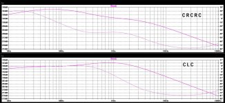
Even if the results I was getting with the CRC were inferior, I then tried something that seems to very promising: CRCRC.
That was a pleasant surprise, because resistors would be very easy to find and implement, and even more: with smaller capacitors.
Using 470uF - 4.7R - 470uF - 4.7R - 470uF resulted in an even better curve than with 1000uF - 3.3mH - 1000uF.
Please take a look and tell me if you agree.
My experience with inductors is zero, but I will try to get some to try anyway. Listening to the resulting supply would be interesting then.
It's time I make my final decisions so I can order the parts, both for the preamps and the power supplies.
The contender power supplies would be the LM317/337 and LT1085 DeNoisers, and the Jung/Didden with no pre-regulator. The latter is because the regulated output on the discrete RIAAs is +/- 30v, so considering the drop on the pre-regulator added to the drop on the Jung/Didden would be critical. The limiting factor is the 317, 337 and 1085 max input voltage, which is 35v.
My first idea had been to try the NoNoiser too, but it's too many things to build. And with the NoNoiser I would like to see some built one first, completely debugged.
But the NoNoiser specs were too good to ignore, so after I build all the stuff I may go back and build a NoNoiser too. Maybe by then someone else already has a NoNoiser pcb design and working supply to pick by.
Attachments
Last edited:
The CRCRC has a better general outlook, but at 100Hz, it is a few dB's from the CLC, but at -180dB, who cares anyway?Using 470uF - 4.7R - 470uF - 4.7R - 470uF resulted in an even better curve than with 1000uF - 3.3mH - 1000uF.
Please take a look and tell me if you agree.
Unless you segment the filter and regulator into a number of well separated shielded blocks, there is no way you are going to arrive at such values in the real world.
You said it perfectly: there is no way you are going to arrive at such values in the real world.
So why should we go for that if that means building an impractical regulator?
My objective is building these regulators, compare their audio characteristics in actual applications, in this case different RIAA preamps, and perhaps help others design and use theirs.
Some of the curves I put here belong in the other thread. But I will upload here the ones belonging to the DeNoiser and the NoNoise.
Hey guys,
Here's my completed pcb ready for testing.
I'll be making a jig for testing this afternoon so I report on my findings later.


I ended up using ZTX851/951 instead of the standard bc327/337 transistors. The pinout of ZTX devices was the opposite of the bc327/337 footprints used on the pcb so you may notice the BJTs are mounted backwards.
Resistors are all Vishay/Dale RN series or CMF series.
Ultra high reliability electrolytic caps have been used throughout. I've selected the electro caps used after the regulators to have as high ESR as was available.
Ceramics caps are X7R types.
Here's my completed pcb ready for testing.
I'll be making a jig for testing this afternoon so I report on my findings later.
I ended up using ZTX851/951 instead of the standard bc327/337 transistors. The pinout of ZTX devices was the opposite of the bc327/337 footprints used on the pcb so you may notice the BJTs are mounted backwards.
Resistors are all Vishay/Dale RN series or CMF series.
Ultra high reliability electrolytic caps have been used throughout. I've selected the electro caps used after the regulators to have as high ESR as was available.
Ceramics caps are X7R types.
Last edited:
- Home
- Amplifiers
- Power Supplies
- D-Noizator: a magic active noise canceller to retrofit & upgrade any 317-based V.Reg.