With all due respect to Diego, it is not a circuit I would recommend: small changes in temperature will severely affect the performance. A decrease will cause the overshoot to reappear, and an increase will cause the transistor to saturate, and a cancellation of the correction as a result.I did the simulation in Ltspice with BC547c (the one I have available at home) and it seems to work by adjusting the trimmer for low VCE.
In addition, a low Vce will limit the dynamic of the correction: if the load draws a non-constant current (a class B amplifier for example), the transistor will saturate at times, causing surges in the output impedance.
If you want to use the scheme anyway, it will work equally well (or poorly) for the negative side, and the transistor type doesn't matter, thanks to the trimmer
Hello everyone,
thanks for the tips.
I was doubtful because some d(i)enoiser/nonoiser are slow at startup, even if the first dienoser gives me good results in the Lspice. (as far as you understand)
This weekend, if I have time, I try to assemble the PCB (± 12v) to understand how it behaves in real life.
Taking inspiration from mark Johnson's project, i created 3 denoisers to feed a TDA1541A DAC, and the results are good (in terms of listening), the tension at the start is quite constant, even if I still have some doubts about the exit post and the relative ESR.
Not having an oscilloscope I can't understand if the regulators oscillate.
How could I understand if I am using CAPs with correct ESR?
Sorry for my banal and inexperienced questions.
Best regards.
Dimitri
The basic denoiser is pretty tolerant as long as you don't use really exotic components: it is designed to work with a large range of run-of-the-mill components, and it will happily do so provided the layout isn't too non-sensical.
With higher perf versions, like the nonoiser or Trileru's iterations, things might be more complicated.
A simple way to detect oscillations is to compare the DC voltages with and without the denoiser in service; see the VRDN thread for practical examples.
Alternatively, you can use an oscillation detector on the collector of the correction transistor, see here for some examples:
https://www.diyaudio.com/community/threads/oscillation-sniffer.264871/post-4121698
When dealing with the CCS Denoisator/NoNoiser I didn't have any obvious oscillations issues. I managed to upset it by completely removing the output cap, or compensation cap. But with output cap installed and 4.7nF-10nF for compensation cap everything seemed stable, at least in audio range. I found it more stable than previous versions I tested.
I might make a probe like yours, I can see about 4 diodes inside the acrylic blob. Which of the three versions from LTSpice screenshot did you use in the pictured probe?

I might make a probe like yours, I can see about 4 diodes inside the acrylic blob. Which of the three versions from LTSpice screenshot did you use in the pictured probe?
I received the new boards, assembled the dual version one and I finished my ADC+LNA gear, so I'll start testing these days.Any news about updated boards and tests?

It is the third schematic: it uses 2 diodes, Ge type, like AA119, OA95, 1N34 or similarWhich of the three versions from LTSpice screenshot did you use in the pictured probe?
Basically, any point-contact diode will do. They are easy to spot: if you look through the glass, you will see the characteristic cat's whisker resting on a small crystal of germaniumI found a few transparent diodes that measure about 0.35V on DMM test. Have no idea what model but they also look like germanium diodes.
Is the model important? Or any germanium diode would do?
The ones I tested were marginally better, but with such unbranded commodities from Asian origin, it is impossible to draw general conclusions: one source could be awful, and another one excellentElvee, would S8050 and S8550 be better options for Denoiser or Dienoiser, instead of BC327 and BC337?
I got to measure different BJTs and there doesn't seem to be much difference for CCS Denoisator. ZTX sat at 3.9nV/sqrtHz level (or 560nV in audio band) and BC560C at 4.6nV/sqrtHz level (660nV in audio band).
What did work nice was using two BJTs in parallel. It does lower the noise by a good bit, and also adds about 6dB of extra PSRR. For Denoisator this is quite a good option.
For NoNoiser the S8550 worked pretty good, noise was similar to BC3x7. For Denoisator the difference between various BJTs was not so great. Using two of them in parallel makes for a lower noise than using say one ZTX.
Also the IR LED from an optocoupler works just as good as a "normal" IR LED.
The extra PSRR seems to work out about 4dB in my case.
Noise seems to work out at a bit less than half. Indeed it halves between two BJTs in parallel at 8mA total and 16mA total. Just adding the second one for the same 8mA total does seem to lower the noisefloor a bit. If I double the current the noise then halves. Overall I got less than half of noise when adding the second BJT, and doubling the current.
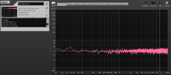
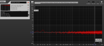
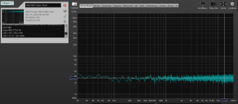
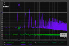
The attached measurements are for LM337 in CCS Denoisator configuration, first one is the noise for a single BC560C as denoiser BJT, 8mA total. Second one two BC560C in parallel at same 8mA total current, third one 2xBC560C with 16mA, and last photo is the PSRR with 110Hz signal.
On the noise measurements total noise in audio spectrum is mentioned on the left side part of the measurement.
Noise seems to work out at a bit less than half. Indeed it halves between two BJTs in parallel at 8mA total and 16mA total. Just adding the second one for the same 8mA total does seem to lower the noisefloor a bit. If I double the current the noise then halves. Overall I got less than half of noise when adding the second BJT, and doubling the current.
The attached measurements are for LM337 in CCS Denoisator configuration, first one is the noise for a single BC560C as denoiser BJT, 8mA total. Second one two BC560C in parallel at same 8mA total current, third one 2xBC560C with 16mA, and last photo is the PSRR with 110Hz signal.
On the noise measurements total noise in audio spectrum is mentioned on the left side part of the measurement.
Attachments
I used the values from this schematic:

If you want to use two BJTs in parallel you need to double C5 value because R7 will need to be around half for same Vce of BJTs. This is to keep the same LF corner frequency.
R6 halves as well to double the current through the denoiser circuit.
Also a good example to show the difference in simulated PSRR with RH117H model and TI's LM317-N spice model. The latter is closer to actual measurement.

1 and 2 are with RH1117H model and 3 and 4 are with TI's LM317-N spice model.
If you want to use two BJTs in parallel you need to double C5 value because R7 will need to be around half for same Vce of BJTs. This is to keep the same LF corner frequency.
R6 halves as well to double the current through the denoiser circuit.
Also a good example to show the difference in simulated PSRR with RH117H model and TI's LM317-N spice model. The latter is closer to actual measurement.
1 and 2 are with RH1117H model and 3 and 4 are with TI's LM317-N spice model.
Each stage composed of 3 transistors could be simplified with one like the original denoiser that starts this thread. It is obvious that this new circuit will require adjustments in the values of its coupling capacitors.
Likewise, all variants will have to be put to the test rigorously, despite the surprising numbers of the simulation.
Best regards
This noise reduction game is completely useless.
Even the connection cables between the output of this module and its load will capture tens-hundred times more noise. And it uses an infinity of pieces. The simple version with 1 transistor is more than enough. Maybe only the slightly more advanced versions with 2-3 transistors.
Even the connection cables between the output of this module and its load will capture tens-hundred times more noise. And it uses an infinity of pieces. The simple version with 1 transistor is more than enough. Maybe only the slightly more advanced versions with 2-3 transistors.
I agree 100%. I only expose a way to overcome those first limits. Afterwards, everyone will choose how they will achieve what they require for their circuits.
I am convinced that there are circuits that do not even require the original denoiser, since the thresholds of a middle ear would not distinguish it.


Best regards
I am convinced that there are circuits that do not even require the original denoiser, since the thresholds of a middle ear would not distinguish it.
Best regards
Last edited:
- Home
- Amplifiers
- Power Supplies
- D-Noizator: a magic active noise canceller to retrofit & upgrade any 317-based V.Reg.