It doesn't change the situation, except if the final output voltage falls within reasonable limits: <40V for example.I was going to use a FET prior the the LM317 to do the heavy work.
Other regulators wouldn't change anything, except if the internal reference is ground-referenced instead of output-referenced. In that case, it is probably possible to work with more palatable dissipations in the components
Hi all,
On a recent pcb order I added some of the boards that @tombo56 kindly proved gerbers for in post 924 - well actually the gerbers were a page or two later, with a small correction for LED polarity.
So building the positive one went smoothly enough, I had to try a few different capacitors for C8 but ended up with a stable and non-oscillating supply. I'm using all parts from the major supply houses, although some have been in storage for a few years. BC327 and BC337, caps resistors etc are all from the same bags as worked OK on the positive reg.
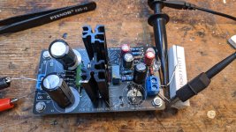
The negative supply though was something different.... no matter what I try I still seem to have oscillation, and the effect is not one I have seen before. It reaches target voltage (~15V, with 20V from lab supply as source for now), and then slowly declines to about 6V, then jumps up again for a second to 15V and so the cycle goes. It does this whether there is a load attached or not.
C6 is 20nF, R11 is 27R as mentioned by @tombo56 in post 924. Ignore the messy board, I have had quite a few caps in and out of there, and if I can tame the oscillations I'll rebuild on a fresh board. The video hopefully shows what I'm seeing.
Any ideas for where I should look next?
On a recent pcb order I added some of the boards that @tombo56 kindly proved gerbers for in post 924 - well actually the gerbers were a page or two later, with a small correction for LED polarity.
So building the positive one went smoothly enough, I had to try a few different capacitors for C8 but ended up with a stable and non-oscillating supply. I'm using all parts from the major supply houses, although some have been in storage for a few years. BC327 and BC337, caps resistors etc are all from the same bags as worked OK on the positive reg.
The negative supply though was something different.... no matter what I try I still seem to have oscillation, and the effect is not one I have seen before. It reaches target voltage (~15V, with 20V from lab supply as source for now), and then slowly declines to about 6V, then jumps up again for a second to 15V and so the cycle goes. It does this whether there is a load attached or not.
C6 is 20nF, R11 is 27R as mentioned by @tombo56 in post 924. Ignore the messy board, I have had quite a few caps in and out of there, and if I can tame the oscillations I'll rebuild on a fresh board. The video hopefully shows what I'm seeing.
Any ideas for where I should look next?
Attachments
I ssem to remember the LM337 dienoiser liked inductance with the output cap. You might try switching to a lower gain transisitor pair, but first i would replace the R10 resistor with a small hand-made inductor. It doesn't take much. I seem to rememeber I used a taller thinner output cap on the LM337 to increase the inductance in the cap also. I just checked, the go to for that circuit was a Panasonic FR series 25V 470uF. Trileru is the guy that has played with these the most, actual circuits. I did get a few of those circuits to be stable, but in some instances I gave up and went back to a standard denoiser. You can do that with that board.
Any ideas for where I should look next?
Uh, unfortunately, there is no way to make LM337 dienoiser version stable. LM317 in dienoiser version is rock stable with any load or output capacitor.
I tested thoroughly LM317 version and enthusiastically added a 337 version as well. However, I didn’t build this one and only later was notified by forum member about stability problems. That was my first and last time to publish project without building it and thoroughly testing prior publishing.
You can use two LM317 versions for bipolar supply or use LM337 version as standard denoiser version. Trileru managed to make stable dienoiser versions with LM337, so you could build those as an better alternative.
I apologize to anyone attempting to build LM337 dienoiser version.
Using designations from schematics at post #924:how to change this to denoiser on the same board?
LM337 – remove Q2 and put jumper instead of R6
LM317 - remove Q1 and put jumper instead of R6

Yes, both stable as denoiser....... will rebuild the negative side on a fresh board and test again - and then maybe test with some different loads.
Thanks, I'll add that little nugget into my notes - maybe this could be inserted into the first post?
Thanks, I'll add that little nugget into my notes - maybe this could be inserted into the first post?
I tested the Dienoiser with a 317, and I had no problem. I also tested the 337 with a regular denoiser, and I managed to make it stable; it wasn't that easy though. I can imagine that the 337+dienoiser combination is much more finicky, but I never tested it.
It can probably made stable, with some efforts. Ask Trileru, he is the expert for such border-line designs.
Otherwise, regress to the standard denoiser for the negative side: it can be made to work properly, and the difference in performance should not matter too much, even for demanding applications.
Conversion from die- to denoiser is pretty easy: omit some components, and install one or two straps
I indeed had some issues with LM337 CCS NoNoiser. I discovered it when using it without a load, it would be unstable. With ~100mA the issue wouldn't manifest. I managed to stabilize it with a small value inductor in series with the output cap. Something like 4-5 turns of thin wire, 1.5-2mm diameter coil. With this inductor I could also use all random output caps I tried, no need for anything special as long as it's under 0.3R ESR.
For LM337+CCS Denoisator I didn't have any issues, but I did have with the normal LM337 Denoisator. 1R-3.3R in series with the comp cap would help a lot. Comp cap 33nF-47nF if I remember right from playing with the regular LM337 Denoisator.
For LM337+CCS Denoisator I didn't have any issues, but I did have with the normal LM337 Denoisator. 1R-3.3R in series with the comp cap would help a lot. Comp cap 33nF-47nF if I remember right from playing with the regular LM337 Denoisator.
Having set up the boards as denoiser for both polarities, I thought it might be useful to look at startup behaviour of both. My reasoning is that 9/10 times if someone is using the neg rail, its not on its own, but in a bipolar supply. The positive rail shows a slight overshoot at the start, and the neg rail is slower to come up to voltage. Both sides have a 1500uF cap at the output, set as denoiser (not dienoiser). Feed is from a 2 x 15V transformer.
Scope is 5V/division vertically (so +/-15V) and 1s per division in time.
Does this look correct to you all? Is there a way to even this up?
Fran
Scope is 5V/division vertically (so +/-15V) and 1s per division in time.
Does this look correct to you all? Is there a way to even this up?
Fran
Attachments
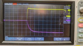

The positive side behaves as in my own setups, but the absence of overshoot on the negative side is somewhat (pleasantly?) surprising.
With the original values, that's not something I expect: are the two coupling caps of the right value, are they properly soldered?
A bit strange, but if the performance is OK, I would see that as an Easter present....
With the original values, that's not something I expect: are the two coupling caps of the right value, are they properly soldered?
A bit strange, but if the performance is OK, I would see that as an Easter present....
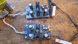
Again, using schematics on post 924 - C5 is 220uF, C7 and C9 are 100uF, C3 and C4 2200uF. Having checked twice, all are properly soldered
C8 is 1500uF 35V, bought from mouser some years back 667-EEU-FM1V152L Panasonic
Same components on both rails, only LM317/337, R11 and C6 on the positive rail is 100nF, C6 on the negative rail is 20nF
Before going off to buy any though, its probably worth verifying everything here is OK! Unfortunately I don't have the tools to measure noise, something I will sort out in the future, so all I can do here is simple measurements.
I meant to add above, these are loaded measurements, 150mA on each rail.
Do both regulators have the same C3 - R2 - C4 values?Both sides have a 1500uF cap at the output, set as denoiser (not dienoiser). Feed is from a 2 x 15V transformer.
- Home
- Amplifiers
- Power Supplies
- D-Noizator: a magic active noise canceller to retrofit & upgrade any 317-based VReg