Looks like good diode drop. In my opinion since you use our usual MUR120 its the EI transformers loss mostly. For instance I am now testing a Talema 50VA 15+15V 1.6+1.6A toroidal. Gives 17.6V unloaded AC each secondary on my 235V now time mains. It just drops to 17.4V AC with a 75 Ohm resistor loading directly one secondary. In other words 4W load for one 25VA secondary.
Changing a hundred times per second. Because its rectification. The scope shows such things very nicely.the readings are not stable.
I decided to measure the AC ripple with an oscilloscope. Against the background of its own noise, there are practically no AC voltage emissions. Am I doing the right thing? Or please tell me how to do it. The output voltage is 17 V. Load 100 R.
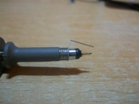
Remember when you use the scope to measure rails select the 20MHz bandwidth limit and use the short coil ground on the probe's nose. To avoid some of the scope's self noise and interference pick up from the normal crocodile long ground lead's inductance.
I've read somewhere that the UltraBib does not like a capacitive load? I'm considering to use a bipolar pair of UBib's to power my Twisted Pear Mercury Output Stage which has 2 330uf caps per rail. Can someone share experiences around utilizing the Ubib with such a load?
Leds can be various. Most reds & greens have steep enough If/Vf curve at low mA. If those available have published data compare their If/Vf curves and choose the steeper one.
I have successfully tested the V1.3 with a 2200uF capacitor connected as load. There is a picture of that somewhere early in the thread. The thing that it does not like is a very low ESR capacitor, say a film capacitor, directly on its output connector.
I have successfully tested the V1.3 with a 2200uF capacitor connected as load. There is a picture of that somewhere early in the thread. The thing that it does not like is a very low ESR capacitor, say a film capacitor, directly on its output connector.
Manniraj, thank you for reminding me. I wanted to ask a question about LEDs. I used Kingbright L-7104LSRD (L-934LSRD) is this replacement acceptable? Thanks.
I hope using this LED was fine in your psu and the voltage is stable without any issues?
Thanks
Hello, I have not tested the regulator very closely yet. The launch was almost without problems, the voltage is regulated, stable. Still, I plan to replace the LEDs with L383SRDT.
Thanks they are a bit expensive, but let me also get few and try in my builds.
Just adjusted my ultrabib with 2.2 ohm resistors. Without a load i get a nice +15v on the positive reg and a -15v on the negative reg.
When i hookup my mercury output stage the positive reg looks dead: the led’s do not glow and the ouput voltage measures a mere 0.26v
The mercury is good, it works with a twisted pear placid hd bp shunt reg set to 270ma ccs set per rail(which shunts 90 ma per rail)
The 2.2 ohm resistor should be good no? (600/270)
Any prime suspects for failure on the positive reg?
Last edited:
It burns the full CCS mA on itself when unloaded. So it worked.
Its most probably current limiting then. You can read what is actually consumed by the load with inserting the DMM in series between the reg + and the load +. Current measuring mode must be selected, use its red Ampere terminal. Min Max function can catch quick current peaks.
Check the voltage drop across the 2.2 Ohm pins. Maybe its not exactly 0.6V. If its actually current limiting due to a start up current peak or something more constant, try 1.5 Ohm if you got one, or parallel some adequate value resistor to the 2.2R for reaching down there as a combination.
Did some more testing:
The mercury output stage draws roughly 155 ma from both POS and NEG rails, a bit less than suspected. Measured this against the Placid HD BP Supply,
This makes me think it cannot be current limiting with R1=2.2R.
Then I hooked up a 75 Ohm 3w to the outputs of the Ubib positive reg, and it worked. Doing the math this should draw 197mA from the Ubib which is set up for 275 mA CCS with R1=2.2R.
Voltage drop across R1 measured 603 mV, so nothing wrong with the Ubib it seems.
But Why it doesn't work connected to the mercury is a riddle.
The mercury has a two input terminals:
- Left Terminal has pos, gnd and neg
- Right Terminal has pos, gnd and neg
The GND positions of both terminals are connected to each other on the mercury board.
I had hooked this up to the Ubib as follows:
- Positive Reg
- positive 'pin' to positive 'pins' of left and right terminals of mercury
- gnd 'pin' to gnd 'pin' of right terminal of mercury
- Negative Reg
- negative 'pin' to negative 'pins' of left and right terminals of mercury
- gnd 'pin' to gnd 'pin' of left terminal of mercury
Due to testing my wires are a tad long: 25 cm or so.
Could my problem lie in hookup and/or wiring?
Last edited:
- Home
- Amplifiers
- Power Supplies
- Salas SSLV1.3 UltraBiB shunt regulator