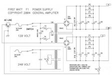
I am observing a strange low level "forest" of noise on the FFT's of my amps using a linear power supply. It is not limited to just this amplifier, currently a Pass M2. I am using a toroidal 400VA 18VAC transformer (Antek) and using the two secondaries tied with a common to make +/-24vdc rails with two separate rectifier bridges and CRC filters. Rectifiers are made using 10A1 diodes in full-wave bridge. Right after diodes are two 330pF 1000v ceramic caps with 10R (0.5W) resistors to GND on each rail as snubbers (not optimized). Then 33,000uF 25v caps per rail with qnty 4 x 0.47R (2w) resistors to next 33,000uF 25v caps (Cornell Dubelier Electronics) with 0.1uF 100v film caps on bypass to GND, Then +/-24v from here has a 5A fuse and then goes to amplifier power inputs.
Here is photo of the amp and PSU in the case (ignore the cap multiplier mounted on heatsink - not used in this discussion, but forest of noise still present with cap multiplier).
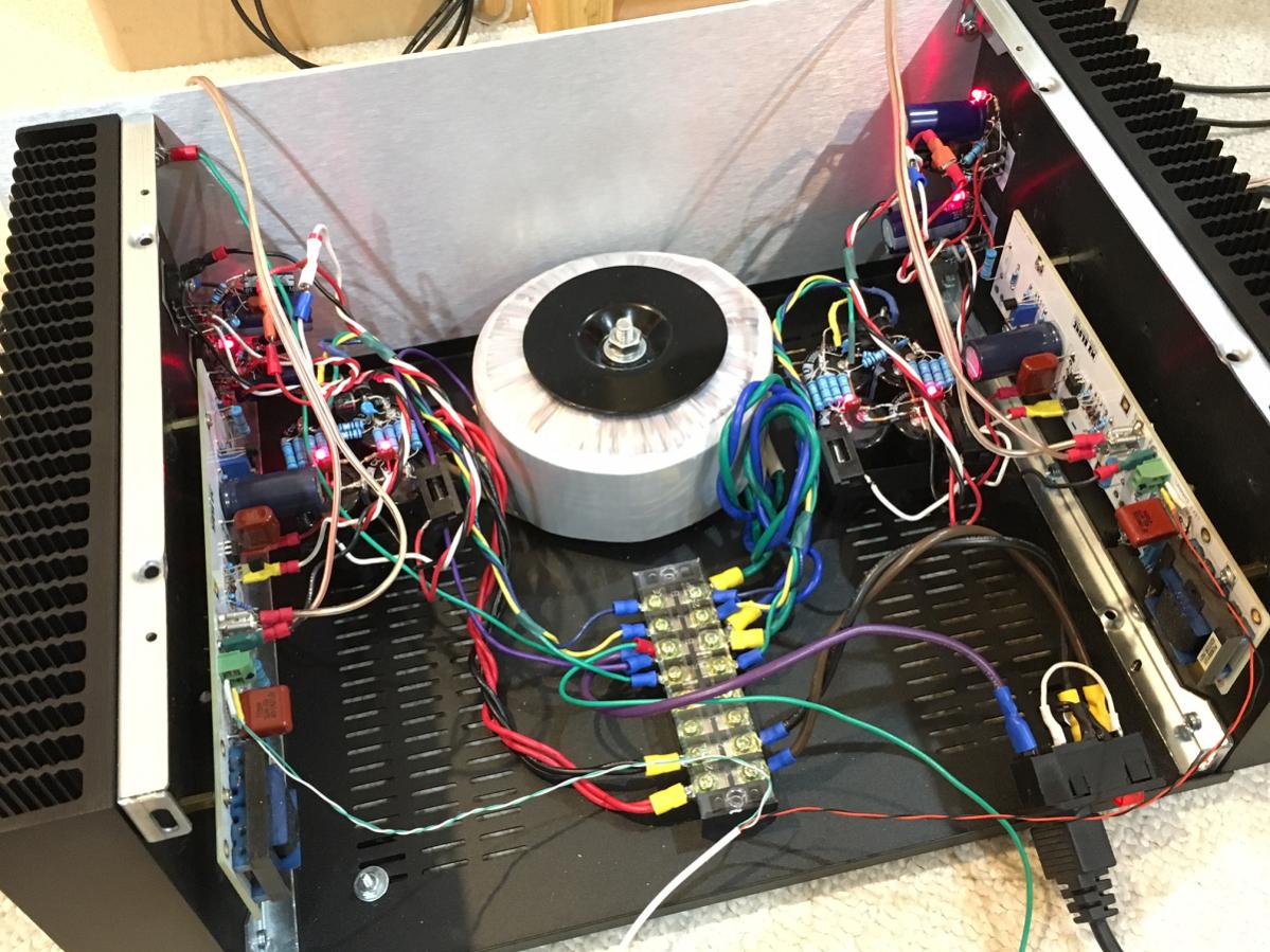
In the photo, you can see the connections from mains to trafo and then trafo secondaries to bridges and CRC (from top terminal: secondary 1, secondary 2, secondary 1 and 2 common connected to system GND and earth GND (terminals 3 and 4 linked to form system STAR GND point here),..., lower two terminals are mains supply (black) and return (brown)).
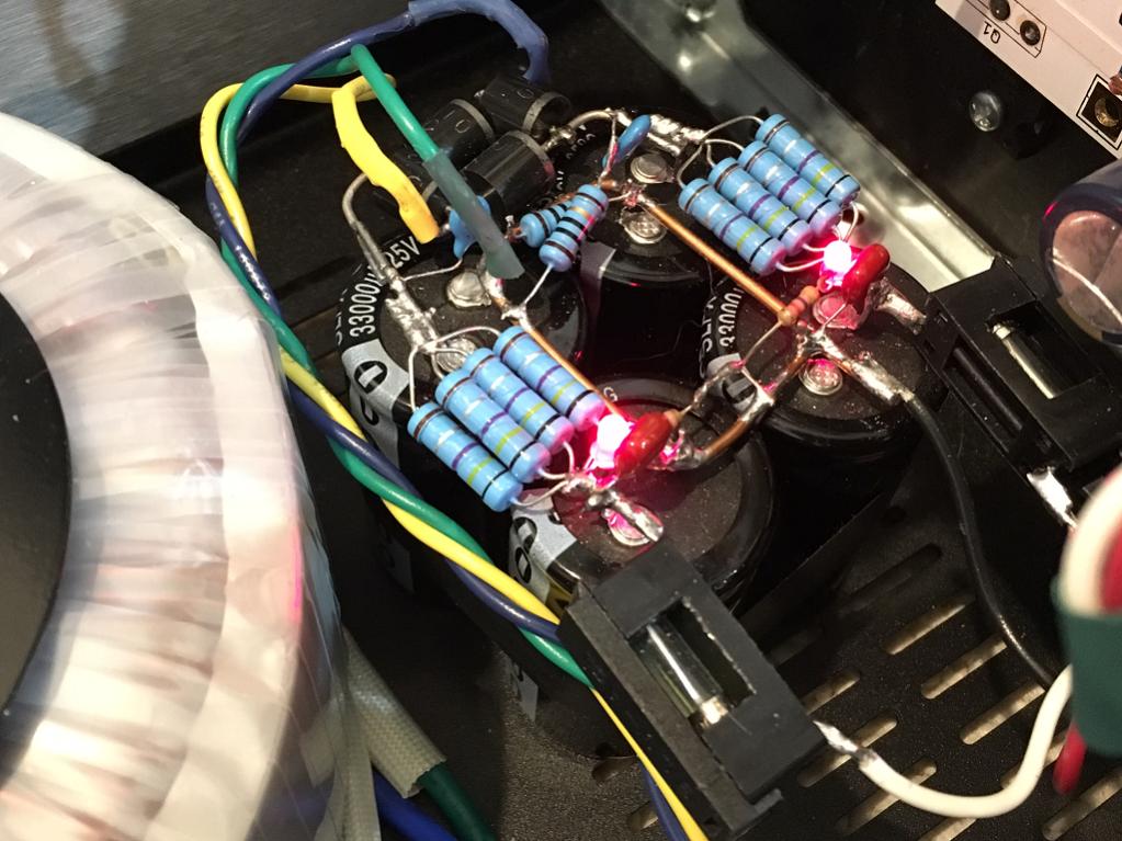
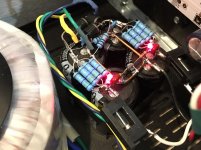
Here is a closeup photo of the diode bridge and CRC filter:
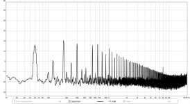
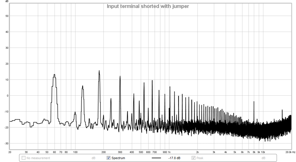
Here is the FFT of the noise at the amp output into an 8R resistive load with the amp audio input grounded. So I see this hash when I run FTT's with an input 1kHz sine. Grounding input did not help so this eliminates input noise pickup.

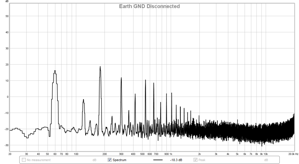
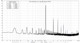
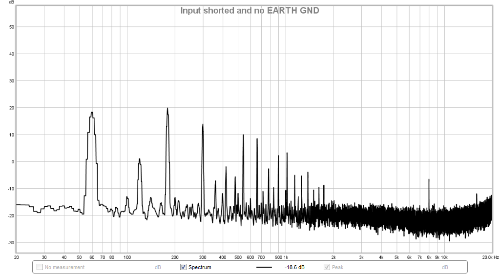
Here is the FFT of the noise with the earth GND disconnected from the amp - less forest of trees hash:
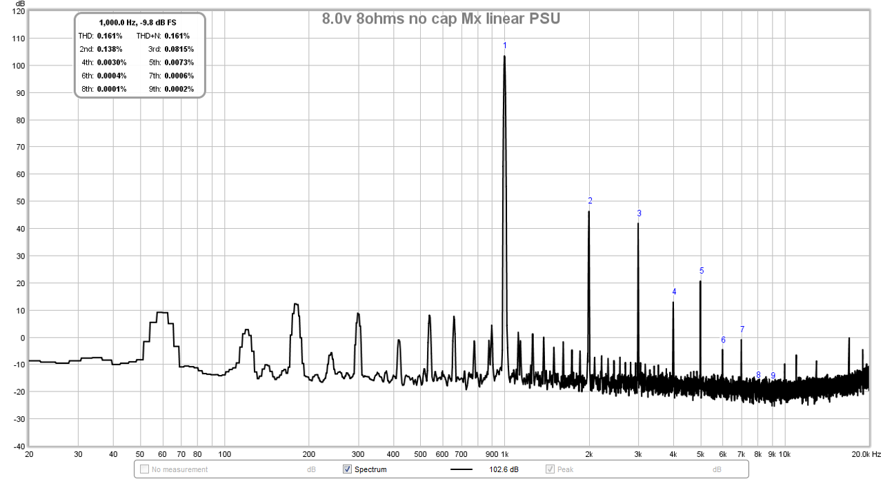
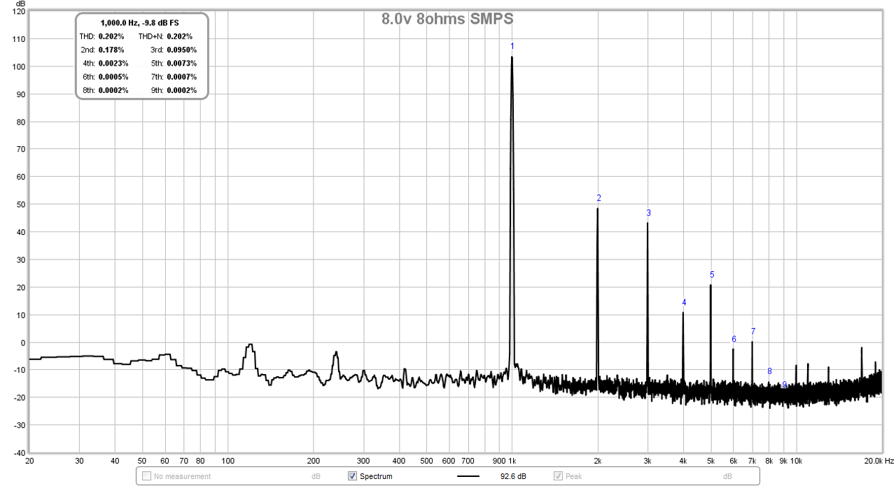
Here is the FFT with the amp driving 1kHz 8v rms into an 8R 35w load:
Substituting the linear PSU for a pair of 24v 5amp SMPS in series (LED light driver bricks), I get a much cleaner FFT with no forest of trees hash:
I am thinking that this is some common fundamental setup problem I am missing here. Linear unregulated PSU's cannot be this noisy, can they? Is this a trafo-cap LC ringing thing? Any suggestions/helpful suggestions to try are welcome.
Listening to it, the hash is audible as a slight hum with ear close to speaker - mostly the large 60Hz peak - which is about -60dB the audio signal at 1w. With the SMPS, there is no audible hum.
Sort of makes me wonder why we bother with massive linear trafos.
One more clue is that the unshielded input wires positioning seems to have impact on amplitude of hash in the higher frequencies. So I used shielded RG174 coax and the hash was still there - just not dependent on position of wires now. Then I grounded it and it is still there.
Here is photo of the amp and PSU in the case (ignore the cap multiplier mounted on heatsink - not used in this discussion, but forest of noise still present with cap multiplier).
In the photo, you can see the connections from mains to trafo and then trafo secondaries to bridges and CRC (from top terminal: secondary 1, secondary 2, secondary 1 and 2 common connected to system GND and earth GND (terminals 3 and 4 linked to form system STAR GND point here),..., lower two terminals are mains supply (black) and return (brown)).
Here is a closeup photo of the diode bridge and CRC filter:
Here is the FFT of the noise at the amp output into an 8R resistive load with the amp audio input grounded. So I see this hash when I run FTT's with an input 1kHz sine. Grounding input did not help so this eliminates input noise pickup.
Here is the FFT of the noise with the earth GND disconnected from the amp - less forest of trees hash:
Here is the FFT with the amp driving 1kHz 8v rms into an 8R 35w load:
Substituting the linear PSU for a pair of 24v 5amp SMPS in series (LED light driver bricks), I get a much cleaner FFT with no forest of trees hash:
I am thinking that this is some common fundamental setup problem I am missing here. Linear unregulated PSU's cannot be this noisy, can they? Is this a trafo-cap LC ringing thing? Any suggestions/helpful suggestions to try are welcome.
Listening to it, the hash is audible as a slight hum with ear close to speaker - mostly the large 60Hz peak - which is about -60dB the audio signal at 1w. With the SMPS, there is no audible hum.
Sort of makes me wonder why we bother with massive linear trafos.
One more clue is that the unshielded input wires positioning seems to have impact on amplitude of hash in the higher frequencies. So I used shielded RG174 coax and the hash was still there - just not dependent on position of wires now. Then I grounded it and it is still there.
Attachments
-
 Dissipante-4U-M2-test.jpg174.7 KB · Views: 3,279
 -
 Background-PSU-Noise.png70.3 KB · Views: 3,040
 -
 Background-PSU-Noise-no-Earth-GND.png69.3 KB · Views: 3,077
 -
 M2-FFT-1kHz-8.0v-8ohms-Right-Channel-No-preamp-Linear-PSIU-No-Cap-Mx.png99.8 KB · Views: 14,998
 -
 M2-FFT-1kHz-8.0v-8ohms-Right-Channel-No-preamp-SMPS.png84.4 KB · Views: 10,229
 -
 CRC-closeup.jpg111.4 KB · Views: 3,272
Last edited:
Does the noise disappear if you remove the wires connected to the amplifier inputs, and then short the input directly at the plugs/sockets on the board ?
Does the noise disappear if you remove the wires connected to the amplifier inputs, and then short the input directly at the plugs/sockets on the board ?
Thanks for the suggestion, and I just tried it...
Unfortunately, no. Just tried shorting it with short 20mm piece of wire.
Connection to EARTH GND disconnected reduces hash in HF's - this is very strange - does it mean my earth GND is noisy?:
Attachments


Last edited:
OK.
I'm wondering then if the problem is physical inducement of the 60Hz caused by the proximity of the transformer to the boards/wiring/circuitry.
Pure ripple on the rails would I think consist of just 120Hz plus harmonics. You would not see that massive 60Hz component. That's one aspect. Maybe you could look at an FFT of the rail and confirm that.
Its possible you have more than one issue as well. Something like the above and a grounding problem.
Also you need to have some idea of how good the basic amplifier design is at rejecting ripple on the rails. If this is a Class A amp then the rail ripple could be large.
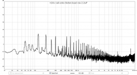
Ok, here is the FFT of the +24v rail via a 2.2uF film cap to 8ohm load. Looks like the hash is in the rail.

It's a Pass M2 design - pretty well praised, and I have not heard of any complaints from others about amp noise or hum. I did try to position the signal transformer at the other end of the amp away from the toroidal trafo. But then it is closer to the terminal strip with 60Hz mains. Although I did not see any FFT's posted by anyone else - mains hum is not that loud and could just be normal? Although typical noise figures quoted by Pass for outputs are in hundreds of microV range with the typical Pass F5 PSU (very similar to my CRC in values).
http://www.diyaudio.com/forums/pass-labs/281520-official-m2-schematic.html
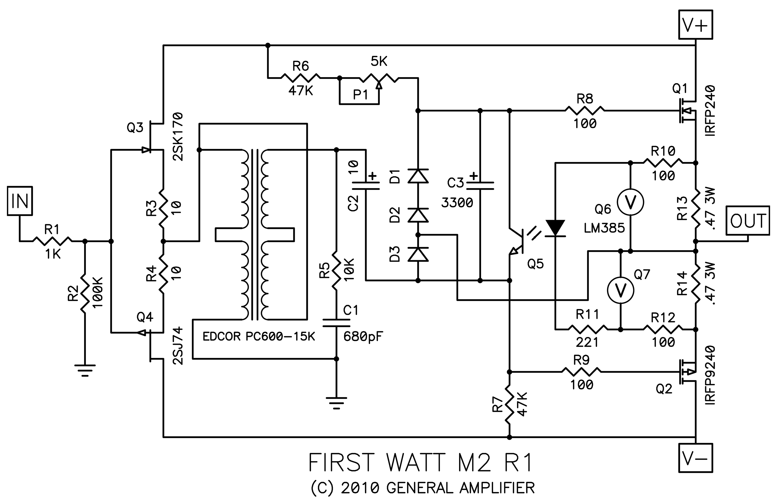
Attachments
Last edited:
There will always be lots of ripple on an unregulated rail, the question is how well the amplifier is able to reject that (its PSRR or power supply ripple rejection ratio). Some of very good (such as opamps and chip amps) and others less so.
Also, a 2.2uf cap and 8 ohm resistor across the rail to measure the ripple (if I'm understanding you correctly) will seriously reduce the true reading. Use a 470k or higher as a load.
You could try as a test removing the transformer and connecting it via flying leads. That would show if there was a problem with induced hum as well as ripple.
Thanks for your help Mooly. I will have to stop for tonight but what do you think of trafo LC ringing? The whole Mark Johnson Quasimodo snubber optimizer tool - would that help?
It sounds like you suspect physical location induced pickup from the transformer?
It sounds like you suspect physical location induced pickup from the transformer?
I suspect both problems tbh, physical and rail ripple. You can 100% eliminate the physical issue by trying it with the transformer removed.
I don't think there is any ringing going on.
One for tomorrow then 🙂
I don't think there is any ringing going on.
One for tomorrow then 🙂
Odd order distortion is caused by transformer saturation. The transformer is probably designed for a 110 volt primary, rated at 115 volts and your line voltage is more like 122 volts. That way the transformer looks like it has better regulation.
Diode noise is even order harmonics.
Try using a 12 volt buck transformer.
Note that other transformers on the power line may also be saturating and putting the harmonics on the line.
Diode noise is even order harmonics.
Try using a 12 volt buck transformer.
Note that other transformers on the power line may also be saturating and putting the harmonics on the line.
Last edited:
This sounds like you have tried to use two separate secondaries with two bridges then joined in series to make a bipolar supply (OK) but then also joined the secondaries to form a CT (not OK). There are two options:xrk971 said:using the two secondaries tied with a common to make +/-24vdc rails with two separate rectifier bridges and CRC filters.
1. two separate secondaries each with their own bridge
2. single CT secondary feeding one bridge
Have you tried to combine them?
This seems to confirm the above, then also seems to suggest that the ground connection is at the dirty end of the PSU.In the photo, you can see the connections from mains to trafo and then trafo secondaries to bridges and CRC (from top terminal: secondary 1, secondary 2, secondary 1 and 2 common connected to system GND and earth GND (terminals 3 and 4 linked to form system STAR GND point here),...
An accurate circuit diagram would help us, but it seems to me that you have got your PSU grounds and charging current loops all mixed up and then injected the resultant buzz straight into your audio ground.
I was trying to make two separate 24v dual rail supplies from a single CT transformer. Is that not possible then?
So to do this supply as dual mono would require two CT transformed?
So to do this supply as dual mono would require two CT transformed?
An externally hosted image should be here but it was not working when we last tested it.
Last edited:
The key word is 'separate', and you can not do that from a common transformer winding/s.
See if any of this helps of which your problem reminds me. You will have to read before and after this point:
http://www.diyaudio.com/forums/solid-state/101321-3-stage-lin-topology-nfb-tappings.html#post1624677
See if any of this helps of which your problem reminds me. You will have to read before and after this point:
http://www.diyaudio.com/forums/solid-state/101321-3-stage-lin-topology-nfb-tappings.html#post1624677
After a bridge rectifier you get 120Hz ripple, not 60Hz.Since the 60Hz seems dominant, perhaps a diode in the bridge malfunctions ?
Mona
Mona
I was trying to make two separate 24v dual rail supplies from a single CT transformer. Is that not possible then?
An externally hosted image should be here but it was not working when we last tested it.
I don't get this, those are separate single rail supplies not dual rail
Yes, now that you mension it 😱 ,more like this 🙂I don't get this, those are separate single rail supplies not dual rail
But where comes the 60Hz peak comes from 😕 still suspecting a diode.
Mona
Attachments
PSU Schematic
Here is what I did - and it sounds like connecting the common tap to GND is a no-no according to comments above. I left off LED and 4.7k resistors as indicators on the output. I need to add 2.2k 2w bleed off resistors still.
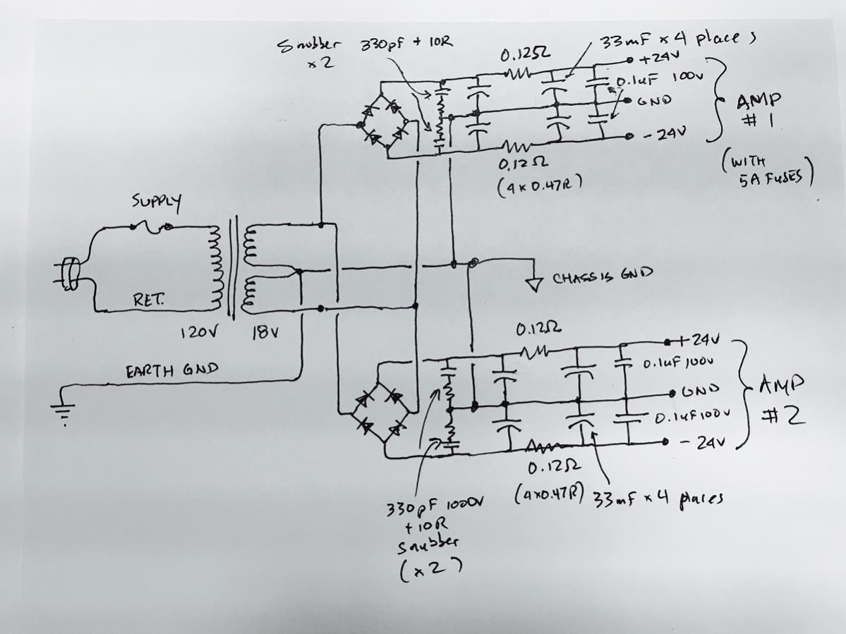
I was trying to get some isolation between the amps via the caps and diode bridges for more of a monoblock psu to enhance imaging and soundstage. Imaging does sound better with this method than a common CRC for both channels. Maybe all I need to do is break the secondary CT connection to GND?
Btw, these are indeed 115v rated trafos according to Antek (model AS4218).
AS-4218 - 400VA 18V Transformer - AnTek Products Corp
My local AC mains power is 120v AC plus or minus 1v as measured with my Fluke 101.
Thanks for all your help.
Here is what I did - and it sounds like connecting the common tap to GND is a no-no according to comments above. I left off LED and 4.7k resistors as indicators on the output. I need to add 2.2k 2w bleed off resistors still.
I was trying to get some isolation between the amps via the caps and diode bridges for more of a monoblock psu to enhance imaging and soundstage. Imaging does sound better with this method than a common CRC for both channels. Maybe all I need to do is break the secondary CT connection to GND?
Btw, these are indeed 115v rated trafos according to Antek (model AS4218).
AS-4218 - 400VA 18V Transformer - AnTek Products Corp
My local AC mains power is 120v AC plus or minus 1v as measured with my Fluke 101.
Thanks for all your help.
Attachments

You don't need centre tap to Earth ground connection for a start. Sorry you've already been told that. Have you disconnected it, see if it helps?
Last edited:
You don't need centre tap to Earth ground connection for a start. Sorry you've already been told that. Have you disconnected it, see if it helps?
Should I break CT connection to main GND connection as well? Basically only use the two ends of the secondaries.
- Status
- Not open for further replies.
- Home
- Amplifiers
- Power Supplies
- Strange Forest of Noise with Linear PSU