Gentlemen, I have started a group buy for ROENDER's (Mihai's) FC-100 amplifier a couple of days ago and am in need of a stable, low-noise PSU to drive the frontend
of the FC-100, giving approx. +/-37 VDC.
I can of course use the shunt-regulator that Mihai originally designed for the FC-100, but I am wondering, if a shunt is still "up-to-date".
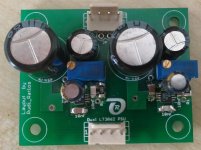
I came across Linear's LT3062, built a prototype (image 1) and did the layout for the "final" PCB (image 2).
The prototype can be adjusted to +/-37VDC flawlessly.
My question: does anyone of you have any experience with the LT3062?
I myself am not able to "measure its performance" (for example: Low Noise: 30μV RMS).
How does it compare to a shunt-regulator?
Best regards - Rudi_Ratlos
P.S.: The 39V Zener is only needed, if somebody's transformer exceeds the allowable specification.
of the FC-100, giving approx. +/-37 VDC.
I can of course use the shunt-regulator that Mihai originally designed for the FC-100, but I am wondering, if a shunt is still "up-to-date".
I came across Linear's LT3062, built a prototype (image 1) and did the layout for the "final" PCB (image 2).
The prototype can be adjusted to +/-37VDC flawlessly.
My question: does anyone of you have any experience with the LT3062?
I myself am not able to "measure its performance" (for example: Low Noise: 30μV RMS).
How does it compare to a shunt-regulator?
Best regards - Rudi_Ratlos
P.S.: The 39V Zener is only needed, if somebody's transformer exceeds the allowable specification.
Attachments
Last edited:
i use the
lt3088
lt3015
lt1963
lt1764
Amazing parts
In addition, I also have the LT3042
But have not used it
Like the LT3062
Output current is 200ma
And need a transistor in output to give a Bost to the Current


[
lt3088
lt3015
lt1963
lt1764
Amazing parts
In addition, I also have the LT3042
But have not used it
Like the LT3062
Output current is 200ma
And need a transistor in output to give a Bost to the Current
[
Last edited:
dazzz, Mihai's FC-100 is only using about 25mA per frontend-power-rail.
So I do not need to boost the current.
The LT3062 is the only LDO that I know, that can be used for such a wide range of voltages: Vin < 45V, Vout < 40V .
Best regards - Rudi
So I do not need to boost the current.
The LT3062 is the only LDO that I know, that can be used for such a wide range of voltages: Vin < 45V, Vout < 40V .
Best regards - Rudi
Last edited:
Yes you should measure it*, AC analysis wont give real results for sub optimal designs and layouts. BTW shouldnt you have had a design review before the 2nd PCB is built and tested? (I can see a few issues even without a schematic posted.) BTW nothing wrong with shunt regulators per se in the right apps. E.g. low current, and stable input DC.
*beg, borrow an analog scope with a LN pre-amp should give some usable results.
*beg, borrow an analog scope with a LN pre-amp should give some usable results.
Last edited:
Rudi reconsider using ground planes. This is infact counter productive for isolating power stages esp. AC-DC rectification to LN regulators.
band gap noise is multiplied up by the ratio to the output, so old fashioned shunts can often beat series regulators for lowest noise.
band gap noise is multiplied up by the ratio to the output, so old fashioned shunts can often beat series regulators for lowest noise.
reading the data sheet the 30uV is spec'd only for Vo = 0.6V ( gain of 1)I myself am not able to "measure its performance" (for example: Low Noise: 30μV RMS).
your noise will be ~ 30uV (Vo/Vref) ~ 2mV RMS it wouldn't surprise me if you can measure 10 mV p-p at 37V DC.
or about 2 divisions at x1 on a good scope using a peak hold function.
Last edited:
reading the data sheet the 30uV is spec'd only for Vo = 0.6V ( gain of 1)
your noise will be ~ 30uV (Vo/Vref) ~ 2mV RMS it wouldn't surprise me if you can measure 10 mV p-p at 37V DC.
or about 2 divisions at x1 on a good scope using a peak hold function.
with all the lt the new lt regs improving transient response
for output voltages greater than 0.6V By adding Cadj cap - CREF/BYP = 10nF

( I usually use c0g/np0 caps for Cadj )
Last edited:
dazz thanks for mentioning Cff , is not only for transient response.
Cff also bypasses the adj pins bandgap noise. Please note the multiplied low frequency noise will not be attenuated until Cff dominates R2. By inspection the Lf corner frequency -3dB can be determined when X(cff) = R2 , Cout >> Cff.
Cff also bypasses the adj pins bandgap noise. Please note the multiplied low frequency noise will not be attenuated until Cff dominates R2. By inspection the Lf corner frequency -3dB can be determined when X(cff) = R2 , Cout >> Cff.
Last edited:
dazz thanks for mentioning Cff , is not only for transient response.
Cff also bypasses the adj pins bandgap noise. Please note the multiplied low frequency noise will not be attenuated until Cff dominates R2. By inspection the Lf corner frequency -3dB can be determined when X(cff) = R2 , Cout >> Cff.
As increase the size the cap CADJ
It takes longer the Voltage Regulators to reach desired voltage
in short SOFT START 😉
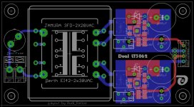
Gentlemen, I have changed the Dual LT3062 PSU - layout (image 1) to:
- accommodate a "bigger" input-buffer-cap (grid: 7.5 x 16)
- decouple the buffer-cap's GND-track from the "Signal-GND-track"
- include a fix SMD adjustment-resistor, the value of which can be temporarily determined by use of the pot
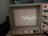
Moreover I have measured the "hum" on the prototype's LT3062 output by means of my old scope.
The output of the LT3062 is loaded by a 1K resistor, resulting in an output current of 37mA.
The "hum" is smaller than one division on the scope, which is 5mV.
I myself think that this dual LT3062 based PSU will do a good job as an amplifier's frontend PSU and will offer it in my FC-100 group-buy.
Thank you, INFINIA and DAZZZ, for your suggestions.
Best regards - Rudi_Ratlos
- accommodate a "bigger" input-buffer-cap (grid: 7.5 x 16)
- decouple the buffer-cap's GND-track from the "Signal-GND-track"
- include a fix SMD adjustment-resistor, the value of which can be temporarily determined by use of the pot
Moreover I have measured the "hum" on the prototype's LT3062 output by means of my old scope.
The output of the LT3062 is loaded by a 1K resistor, resulting in an output current of 37mA.
The "hum" is smaller than one division on the scope, which is 5mV.
I myself think that this dual LT3062 based PSU will do a good job as an amplifier's frontend PSU and will offer it in my FC-100 group-buy.
Thank you, INFINIA and DAZZZ, for your suggestions.
Best regards - Rudi_Ratlos
Attachments

Gentlemen, I have changed the Dual LT3062 PSU - layout (image 1) to:
- accommodate a "bigger" input-buffer-cap (grid: 7.5 x 16)
- decouple the buffer-cap's GND-track from the "Signal-GND-track"
- include a fix SMD adjustment-resistor, the value of which can be temporarily determined by use of the pot
Moreover I have measured the "hum" on the prototype's LT3062 output by means of my old scope.
The output of the LT3062 is loaded by a 1K resistor, resulting in an output current of 37mA.
The "hum" is smaller than one division on the scope, which is 5mV.
I myself think that this dual LT3062 based PSU will do a good job as an amplifier's frontend PSU and will offer it in my FC-100 group-buy.
Thank you, INFINIA and DAZZZ, for your suggestions.
Best regards - Rudi_Ratlos
The best cap From my experience )in/output) is
Vishay Solid Tantalum Chip Capacitors, TANTAMOUNT™,
Ultra-Low ESR, Conformal Coated, Maximum CV
View attachment 597d.pdf


Determine frequencies on random noise. It may be just a ground loop 50Hz or residual 100Hz rectified component and possibly some nearby SMPS HF spikey stuff. Use the 'line trigger' setting to see if truly random. E.g. is hum (line related) or hiss (random noise)?
notes on layout
1) reroute minus connection to 1000uF terminal ( disconnect short trace coming from the rectifier side) This makes a difference E.g. avoid noisy grounds ) ideally it then goes to 1 uF cap which then defines the ground heaven point or ground plane if any.
2 ) route feedback sense lines from gain setting resistors to the output connector or 100 uF cap..
Last edited:
The best cap From my experience )in/output) is
Vishay Solid Tantalum Chip Capacitors, TANTAMOUNT™,
LT often specifies tantalum on their data sheets, BUT lots of folks have had really bad experiences with them from the seventies and early eighties.🙁
I find modern Al electrolytics picked wisely with smart layouts can often beat "better" parts.
2 ) route feedback sense lines from gain setting resistors to the output connector or 100 uF cap..
sense lines to output > less important for low current supplies, but a good habit nonetheless.
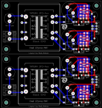
Gentlemen, I have ordered 10 of "my Dual LT3062-based - PSUs" (see image attached) a minute ago.
The prototype is working very well and can compete (even outperform - in my ears) with a Shunt-PSU.
I myself will (want to) use this PSU as frontend-PSU for ROENDER's (Mihai's) FC-100 (needing: +/-37VDC).
The input voltage range of the LT3062 can be as much as 45V. Its output voltage may be adjusted to as much as 40V.
You can adjust the output-voltage by either a potentiometer or a fix-value SMD-resistor.
You can either use a TAMURA- (rated at 115 VAC resp. 230 VAC) or a EI42-230VAC transformer.
As you can see from the attached image, I have implemented a "Star-GND", the position of which is the 1µF input capacitor.
A PCB (100x100mm) contains two Dual-LT3062 PSUs; the PCB is milled in the mid of it, and you will be able to easily break it into two parts.
Five of these PCBs are available.
One PCB costs 8€; shipping worldwide is inclusive.
If you like to have a PCB: tell me.
Best regards - Rudi_Ratlos
Attachments


dazzz,
in case you are interested
i have ordered 2 of each for test for 3.3v digital (pcm1794):
-lt1763 (500mA)
-adm7170
-lt3088
-lp5907
they should arrive tomorrow...
pidesd this is the the photo of my project that you ask and steve vai my cat


- Status
- Not open for further replies.
- Home
- Amplifiers
- Power Supplies
- LT3062 based PSU