ok thanks...now i see the pics 🙂
replacing capacitors with better ones with less distortion (film,etc) can have benefits, but i'm careful whenever i do this...if i'm not sure if it sounds better, it probably does'nt!
also, i tried a POSCAP (tentalum-polymer) and haven,t found it sounds good for some reason, just like polymer-aluminium capacitor (great bass but harsh on higher frequency).
Anyway, i might retry the POSCAP (so expensive) to be sure...
edit: my cat has actually no official name...but i could name it ''Buckethead'' maybe.... 🙂
Last edited:
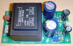
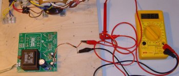
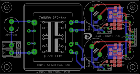
Find attached two images of my "Dual LT3062-PSU" - prototype.
It could be easily adjusted to about +/-36VDC.
I have already connected it as "frontend-PSU" to my SYMASYM - and the LT3062 does quite a good job.
Best regards - Rudi_Ratlos
It could be easily adjusted to about +/-36VDC.
I have already connected it as "frontend-PSU" to my SYMASYM - and the LT3062 does quite a good job.
Best regards - Rudi_Ratlos
Attachments
Yeah, those LT3062 are super duper tiny! I've got 8 of them on hand.
I think I can deal with the leads using a drag or solder wick technique.
Not sure how to deal with the underside of the package that should be soldered to the board. I've got a powerful iron I can use on the backside of the PCB. Presumably this needs to be done before soldering the leads? Or alternatively I have a reflow oven and I could use a dab of solderpaste and reflow it, then hand solder the leads. Don't have a stencil that'll work.
Recommendations?
BK
Use a stencil and your reflow oven.
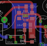
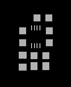
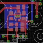
This is how I connected the LT3062' back to GND (see the image).
I have layed out a GND-plane(blue) beneath the IC, inserted 2 holes (VIAs) into it and put 2 little drops of solder tin into these holes.
The solder tin then connects to the back of the IC.
In this way the GND-plane provides some cooling.
Best regards - Rudi_Ratlos
Attachments
Use a stencil and your reflow oven.
This is how I connected the LT3062' back to GND (see the image).
I have layed out a GND-plane(blue) beneath the IC, inserted 2 holes (VIAs) into it and put 2 little drops of solder tin into these holes.
The solder tin then connects to the back of the IC.
In this way the GND-plane provides some cooling.
Best regards - Rudi_Ratlos
Yes, reflow would be the most correct/predictable method. If it's going into the oven might as well do all the (top) SMD components as well.
Rudi, if you can share the board files with me, or at least the small section including all the electrolytics, I'd be happy to have a stencil made and give it a go. The smaller the total area the cheaper the stencil is!
BK
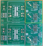
BK: compare the two attached images.
Is this, what you want?
P.S.: I do not know, which revision of the LT3062 PCB you own.
Best regards - Rudi
Rudi: see the pic below of the PCB I have (previous gift from you).
I could get a stencil for either the whole PCB, or just the parts with surface mount components to save some money. But, there needs to be enough surrounding area for me to tape down, etc. See the red and yellow boxes for examples for reflow of complete or separated PCB, respectively.
BTW, I use OSH Stencils. Also below is an example of a previous project with a polyimide stencil. I might use a stainless steel stencil for this.
BK
Attachments

Hi, please give me your EMail address, so I can send you the Gerber files of the LT3062 PSU.
Best regards - Rudi
Best regards - Rudi
I'm having 10 PCBs made including a stainless steel stencil, so the SMD components can all be reflowed including the very tiny LT3062 chip. Rudi will take a couple of reflowed boards, but if anyone else is interested just let me know. You'll be responsible for the through-hole stuff and cost will be parts + shipping. Will update here after a successful build. Timeframe should be 2-3wks.
BK
BK
So are you saying all the SMD components will already be soldered to the board and all that's needed for a completed board is installing all the thru-hole components?
So are you saying all the SMD components will already be soldered to the board and all that's needed for a completed board is installing all the thru-hole components?
Yes, exactly. You separately buy and install the TH parts.
BK
BK...a couple more questions:Yes, exactly. You separately buy and install the TH parts.
BK
Just to be sure here, is one board for a bipolar supply?
If so, is "V2" +V and "V1" -V?
Do the boards have a provision for the Tamura 3FD transformer like Rudi's?
As for thru-hole parts, I see 4 'lytic caps, a couple of .01uF caps and a couple of what looks-to-be 3296Y trimmers.
Even looking at the BOM I can't figure out what value the trimmers are.
What is the purpose of the jumper JP?
Price for your boards?
Just to be clear, these are based on Rudi's most recent Gerbers and therefore it is his exact layout primarily intended as a front end supply for the FC-100 amp in lieu of the traditional shunt supply. Due to the challenge of hand soldering the crazy small LT3062 chip, I'm simply stepping in procure some boards and a stencil and press my reflow oven into service. I'll post a BOM for input sometime soon. Will let Rudi comment on other aspects of the design.
BK
BK
Part list proposal below. Happy to get input on specific component choices:
1000uF, 63V, 105C, Panasonic FC EEU-FC1J102
100uF, 63V, 105C, Panasonic FC EEU-FC1J101L
100kohm, 1%, 100ppm, 1206, thick film, Vishay CRCW1206100KFKEA
50kohm trimmer, TT Electronics, 64YR50KLF
0.01uF MLCC, 50V, COG, 5%, 1206, Murata 64YR50KLF
1uF MLCC, 50V, X7R, 10%, 1206, Murata GRM31MR71H105KA88K
10uF MLCC, 50V, XR5, 20%, 1206, Murata GRM31CR61H106MA12L
Bridge rectifier, DF4, surface mount, Comchip DF04S-G
LT3062, MSOP8
6VA 2x28V transformer, Tamura 3FD-456
Input connector, 5mm pitch ?? tbd
Output connector ?? tbd
Mini-fuse ?? tbd
BK
Ammel, since I myself am not able to solder the tiny LT3062 in MS-8 package, I have given Bob the Gerber files of my layout and asked him to order a couple of these PCBs.
The PCB implements two independent LT3062 - PSUs, but by putting a cap across JP1 you can make it a +/- PSU: for example: a +/-37VDC PSU to drive the frontend of your FC-100
or a +/-15VDC PSU to drive a Muses chip. You need an appropriate transformer though (for example: Tamura 3FD-456; the PCB also supports EI42-case print transformers).
There is one reservoir electrolytic cap (1000µF) on the input and a smaller one (100µF) on the output of each PSU.
For the sake of convenience I am using a 50K potentiometer to adjust the output-voltage. You can as well use the SMD-resistor labelled "?K", if you do not like the potentiometer.
If you ever need a PSU with output voltage 20VDC < Vout < 40VDC and "nice" load and line regulation characteristics, I recommend this one to you.
Best regards - Rudi_Ratlos
Attachments
Thanks Rudi and BK for the replies.
Actually, I'm looking for +/-12VDC supply for op-amp circuits.
Is it possible to get this voltage with the 50k trimmers?
For that output voltage, I figure I should be able to use a 12V x 2 transformer.
That EI42 case transformer looks pretty nice. I'll see if Mouser carries those.
If so, I can compare prices for the Tamura vs. a EI42 style transformer.
What size cap goes across JP1 to make this a bipolar supply?
BK, any idea on price for the board with all the SMD parts already soldered?
- Status
- Not open for further replies.
- Home
- Amplifiers
- Power Supplies
- LT3062 based PSU