Can I assume that the difference between the regular version and the 'X' version of diodes on the schematic are for different size packages?
Regards,
Dan")
Answer on BOM. ;-)
I'm using this for a vfet diy psu. 22v transformer.
If the bleeder resistor is only used to discharge the caps after power off, why does it have to be a 3W ?
28V and 15k resistor, then power ~ 0.05W
What am I missing?
Thanks
A 3W resistor will probably have a long, uneventful service life within the design parameters. If you want to get into more detail, there is an excellent 'capacitor discharge calculator' on Digikey's website:
Capacitor Safety Discharge Conversion Calculator | DigiKey
The value of the resistor and its power rating have much to do with how quickly you want the capacitor to discharge. Play around a bit and see for yourself, but generally you'll find that for more rapid discharge times (i.e. lower resistance) the power rating goes up.
Decide on a reasonable value (the BOM values look fine) then multiply the power rating by 2 or 3 for a long service life.

This was covered in post #773
You are looking at the BOM for a different amp than a Firstwatt. The values are printed on the schematic for the generic PassDIY 25W amp;
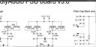
May I ask if the orientation of the secondary windings matter in this setup ? Interesting to see that they differ between the two bridges, the upper winding end go one the first bridge to the left of the bridge, on the the second to the right side of the bridge. Is this intentended or a flaw ?
Last edited:
As drawn those bridges are symmetrical right-to-left, so the upper and lower wirings aren't really different.
But FWIW, orientation of the secondaries is only critical if you're converting a dual secondary to a centre-tapped (ie: using a single bridge rectifier with two secondaries). As I understand it, anyway....
But FWIW, orientation of the secondaries is only critical if you're converting a dual secondary to a centre-tapped (ie: using a single bridge rectifier with two secondaries). As I understand it, anyway....
Hi guys, is there anyone that can answer to my question? I need to know this because I ordered the tranformer with two 45V secondaries, but I actually don't know if the manufacrurer will send me it center tapped or with two separate secondaries. In this last case it's possible to use a double rectifier, but with the center tapped I believe not. From this situation arises my doubt. Can anyone help me, please?Hi, just one question. May I use the double filter section (8 caps) with only one rectifier? This just because I have a center tapped transformer. Many thanks.
Gaetano.
Thank you very much.
Gaetano.

First of all, thank you for your kind answers. As you have likely noted, I am a biginner diyer, so I would like to have clear ideas before starting building this project. Actually, I don't know which kind of transformer they will bring, but let's suppose they send me the CT type. I'm now waiting for the universal PS board, which I ordered some days ago. My concern now is this: using a CT, for what I have understood, implies the use of just one rectifier. Considering that the filter part of the board consist of two almost symmetrical parts, I have to connect the only rectifier to one board with four filter caps. But I wish to use all the eight caps. So, I have to somehow join each other the two filter boards.How can I achieve this? How to manage the ground? I'm sorry for my newbie questions, but as I mentioned before, I'm a beginner!
Thank you very much,
Gaetano.
Thank you very much,
Gaetano.
Ops, actually I omitted to speak about my project. I'm planning to build a power amp, which I would like to use either as a full band or as a low pass filtered one to power up my homebuilt 4 ohm subwoofer. I already build an amp like this, using ljm l25d modules and Connex SMPS800RE and before that another one with two Hypex ucd700 and two SMPS1200A700. But now I felt like trying linear PS and because of my passion for class D amps, I bought two Connex Cxd400. But building this now is a bit more complex than before. While in the last amps, SMPS was ready to use, this linear one is not and I have to build it narly from scratch. So I began studying, for what I can, linear PS, trying to understand them as much as possible (also this from scratch!). I will see what I will be able to do. But probably I will ask you some help again!
Gaetano.
Gaetano.
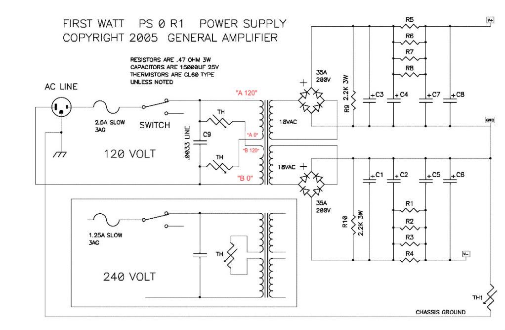
If you follow the diagram from 6L6s post above (lower one) that shows you exactly how to connect things in the case of a ct and single rectifier. In his illustration there is a single cap per rail, but the overall arrangement is the same.
Thank you for the answer. I understand that a rectifier only can be used to obtain dual voltage from a CT tranformer. But unfortunately for me it's not enough. I'm sorry to admit that you have to think at me like a child that needs to learn everything step by step. Theory (at a very basic level) is almost clear. Now I need to discuss it at a practical level, i.e. how to realize it on the pcb.

If I keep only a rectifier, but I want to mantain the whole filter board, how can I join the part 1 with the part 2? How must I manage ground? Ground comes from the 0V of the transformer and should enter the filter board. Where?
Cheers,
Gaetano.
I am embarking on my 2nd build of a Pass amp and want to build my PSU with the future in mind, even though we dont know what we dont know . 50V, 10mm leads & 35mm diameter. Will really only be for F4/F5/Aleph and M2X in meantime and hopefully any other future Pass amps. Any other specs I need to look for with capacitors and is it only capacitors I need to watch out for (provided I know what the transformers secondary voltages are)?
Are there any other Pass amps that deviate from the dual 18VAC secondaries and require a more heftier transformer?
btw I have built many other kits not related to this site and used my bulb tester (mentioned many times by Andrew and 6L6) and it has saved me on parts and troubleshooting, so for those new to building please build one. Its really cheap, easy and worth it.
Thx
Neville
. 50V, 10mm leads & 35mm diameter. Will really only be for F4/F5/Aleph and M2X in meantime and hopefully any other future Pass amps. Any other specs I need to look for with capacitors and is it only capacitors I need to watch out for (provided I know what the transformers secondary voltages are)?Are there any other Pass amps that deviate from the dual 18VAC secondaries and require a more heftier transformer?
btw I have built many other kits not related to this site and used my bulb tester (mentioned many times by Andrew and 6L6) and it has saved me on parts and troubleshooting, so for those new to building please build one. Its really cheap, easy and worth it.
Thx
Neville
Last edited:
- Home
- Amplifiers
- Power Supplies
- diyAudio Power Supply Circuit Board v3 illustrated build guide