
Just like the board I have (forget who I bought it from - someone on the list).
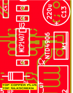
But the NTD4906 is obsolete. I substituted an IRFU7546 with 60V Vdsmax, Idmax of 56A and an on-resistance of 0.0066 ohms. Pulsed drain current of 280A. Rise time 28ns, fall time 20ns. About £0.86 so about a buck each. Also d-Pak and a drop-in replacement. Works a treat.
Craig
But the NTD4906 is obsolete. I substituted an IRFU7546 with 60V Vdsmax, Idmax of 56A and an on-resistance of 0.0066 ohms. Pulsed drain current of 280A. Rise time 28ns, fall time 20ns. About £0.86 so about a buck each. Also d-Pak and a drop-in replacement. Works a treat.
Craig
Good old octopart.com found 40,000+ units of NTD4906. They are on the shelf and ready to ship, at Arrow. For USD 0.20 per piece.
https://www.arrow.com/en/products/ntd4906na-1g/on-semiconductor
I bought 100 of them a year ago and apparently Arrow still has quite a few remaining. These are awfully good MOSFETs, with a quite outstanding (QGtot * Rdson) figure of merit: (6.5 milliohms * 11 nanocoulombs) = 72 pico volt-seconds. I'm not aware of another MOSFET whose figure of merit is nearly this low. For twenty cents, they're a screaming bargain.
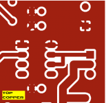
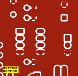
I downloaded the Thru Hole Gerbers (.zip archive) attached to post #1 of this thread, and used the free online Gerber Viewer at www.pcbxprt.com to study them. Here are a couple of screenshots in the vicinity of the MOSFET. I wasn't too concerned about the soldermask layers and didn't even view them.
_
_
Attachments
Thanks Mark. Just order 100 of them. So any guys here in Australia want some the should arrive on the 28 of April. Send me a PM.Good old octopart.com found 40,000+ units of NTD4906. They are on the shelf and ready to ship, at Arrow. For USD 0.20 per piece.
https://www.arrow.com/en/products/ntd4906na-1g/on-semiconductor
I bought 100 of them a year ago and apparently Arrow still has quite a few remaining. These are awfully good MOSFETs, with a quite outstanding (QGtot * Rdson) figure of merit: (6.5 milliohms * 11 nanocoulombs) = 72 pico volt-seconds. I'm not aware of another MOSFET whose figure of merit is nearly this low. For twenty cents, they're a screaming bargain.
Good old octopart.com found 40,000+ units of NTD4906. They are on the shelf and ready to ship, at Arrow. For USD 0.20 per piece.
https://www.arrow.com/en/products/ntd4906na-1g/on-semiconductor
I bought 100 of them a year ago and apparently Arrow still has quite a few remaining. These are awfully good MOSFETs, with a quite outstanding (QGtot * Rdson) figure of merit: (6.5 milliohms * 11 nanocoulombs) = 72 pico volt-seconds. I'm not aware of another MOSFET whose figure of merit is nearly this low. For twenty cents, they're a screaming bargain.
I absolutely agree that you worked very hard to identify the best part for Quasimodo - and a very fine and useful thing it is too, thank you!
But the overall switching time of the MOSFET is going to be dominated by inductive effects - in the circuit board traces, the self-inductance of the capacitors, and in the wiring to the transformer under test.
In any event I'm in despair with OnSemi's policy of obsoleting any half way useful silicon such as the NTD4906. Their recent obsoleting of the MPSA06/MPSA56 (and the MPSW high power variants) is another irritating case in point.
Craig
Edge speed oscilloscope waveforms for thru-hole Quasimodo are shown in post #297 of this thread. The bell-ringing stimulus WHACK! when the NMOS turns on, slews at 4600 volts per microsecond. Steeper than high speed digital logic ICs in thru-hole packages.
Measurements on the follow-on, cost reduced "Cheapomodo" design, prove that a perfectly useful test jig need not have an incredibly low output resistance. Cheapomodo's output resistance is several hundred milliohms, compared to TH Quasimodo's six milliohms, yet Cheapomodo gives equally good snubber-optimization waveforms. Thus a super-motivated person could embark on a parts hunt, seeking the lowest QGtot MOSFET in active production, whose RDSon is (let's arbitrarily say) 300 milliohms or less. I expect this would give significantly steeper slew rate than the NTD4906's 4600 V/us. Could be a lot of fun! Unnecessary, but fun.
Measurements on the follow-on, cost reduced "Cheapomodo" design, prove that a perfectly useful test jig need not have an incredibly low output resistance. Cheapomodo's output resistance is several hundred milliohms, compared to TH Quasimodo's six milliohms, yet Cheapomodo gives equally good snubber-optimization waveforms. Thus a super-motivated person could embark on a parts hunt, seeking the lowest QGtot MOSFET in active production, whose RDSon is (let's arbitrarily say) 300 milliohms or less. I expect this would give significantly steeper slew rate than the NTD4906's 4600 V/us. Could be a lot of fun! Unnecessary, but fun.
The results posted here were all generated with the transformer secondary winding under test connected to the Quasimodo or Cheapomodo test jigs, while all other primary and secondary windings were shorted. A rectifier of any kind was not involved as the test jig itself provides the ringing stimulus.
There's a separate thread detailing the test jig function and a paper about theory of the topic as well as the snubber optimisation method.
Greetings,
Winfried
Thanks Winfried.
So basically the numbers will be the same for any rectifier for the transformer used in the testing. Right?
Last edited by a moderator:
The short answer is: Yes!... the numbers will be the same for any rectifier for the transformer used in the testing. Right?
Folks,
sorry for the off-topic!
Winfried
The short answer is: Yes!
Thanks a lot Winfried for teaching me. Appreciated!
Hi everyone,
Please free to reply to any and all messages here. Just because a message begins "Person_X, I want to ask you a question" doesn't prevent anyone else from responding. If you would like to contribute your comments, wisdom, opinions, and so forth: please do so.
Please free to reply to any and all messages here. Just because a message begins "Person_X, I want to ask you a question" doesn't prevent anyone else from responding. If you would like to contribute your comments, wisdom, opinions, and so forth: please do so.
A couple of days have passed with no replies from anyone.
It's important to know that the title of this diyAudio discussion thread, the one you are reading right now: Simple, no-math transformer snubber using Quasimodo test-jig, has been compressed for brevity. And also so it will fit in the Index of the Forum. A more descriptive and more accurate title would be
Quasimodo is a finesse; it gets to the end result of a rather complicated piece of laboratory measurement, plus a rather involved set of mathematical calculations, without requiring the user to do any complicated lab work, or to make any mathematical calculations at all. The design and operating instructions of Quasimodo, manage to hide the EE complexities behind an unusual circuit design and a straightforward, simplistic lab procedure. When you're using Quasimodo you're actually doing some mildly sophisticated Electrical Engineering; you just don't know it. If you are dying of curiosity, if you are desperate to know what's going on "under the hood", take a brief glimpse at the EE stuff which Quasimodo hides away. It's all discussed in excruciating detail within Jim Hagerman's technical article. It is pretty heavy going.
The lab measurements required, are not easy. You must measure the self-inductance of the transformer secondary, at the oscillatory ringing frequency of the RLC secondary circuit. (Why? Because secondary leakage inductance, unlike ideal textbook inductance, varies with frequency). Check out what Hagerman has to say about it, on page 5. Not so easy.
Secondary leakage inductance is especially troublesome. It's the fraction of inductance which is not magnetically coupled to the transformer core, and not magnetically coupled to the other windings (primaries and secondaries). How do we reduce these other inductances to ~ zero, so that we can measure leakage inductance and ONLY leakage inductance? We short them out. We short all of them out. All other secondaries (except the secondary being measured): shorted. All primaries: shorted. Now what remains is ~ only the leakage inductance of the secondary under test.
And that's my answer to question 1 above. You do it because it gives the correct result.
For question 2 my answer is: the results would be wrong
So I guess I will make an attempt to answer:1. why you short the other side - primary?
2. what kind of results you get if you would use Quasimodo with primary open?
It's important to know that the title of this diyAudio discussion thread, the one you are reading right now: Simple, no-math transformer snubber using Quasimodo test-jig, has been compressed for brevity. And also so it will fit in the Index of the Forum. A more descriptive and more accurate title would be
Simple transformer snubber using Quasimodo test-jig, requiring no EE training and no EE mathematics
Quasimodo is a finesse; it gets to the end result of a rather complicated piece of laboratory measurement, plus a rather involved set of mathematical calculations, without requiring the user to do any complicated lab work, or to make any mathematical calculations at all. The design and operating instructions of Quasimodo, manage to hide the EE complexities behind an unusual circuit design and a straightforward, simplistic lab procedure. When you're using Quasimodo you're actually doing some mildly sophisticated Electrical Engineering; you just don't know it. If you are dying of curiosity, if you are desperate to know what's going on "under the hood", take a brief glimpse at the EE stuff which Quasimodo hides away. It's all discussed in excruciating detail within Jim Hagerman's technical article. It is pretty heavy going.
The lab measurements required, are not easy. You must measure the self-inductance of the transformer secondary, at the oscillatory ringing frequency of the RLC secondary circuit. (Why? Because secondary leakage inductance, unlike ideal textbook inductance, varies with frequency). Check out what Hagerman has to say about it, on page 5. Not so easy.
Secondary leakage inductance is especially troublesome. It's the fraction of inductance which is not magnetically coupled to the transformer core, and not magnetically coupled to the other windings (primaries and secondaries). How do we reduce these other inductances to ~ zero, so that we can measure leakage inductance and ONLY leakage inductance? We short them out. We short all of them out. All other secondaries (except the secondary being measured): shorted. All primaries: shorted. Now what remains is ~ only the leakage inductance of the secondary under test.
And that's my answer to question 1 above. You do it because it gives the correct result.
For question 2 my answer is: the results would be wrong
Thanks Mark and I will give a parts stuffer answer. Because your measurements are ****without shorting... I had one of mine open as the short failed and was looking at the scope thinking wtf? I could not get any usable results and it fact I wasn't even looking at the relevant portion of the waveform.
Hi folks,
I hope a component choice question (due to personal inexperience) is acceptable here:
On my transformer is one winding which supplies 330V. For the according snubber circuit I guess I need 400V mylar capacitors, BUT which kind do I choose out of the widespread offering? I see e.g. Wima FKS-2, FKP-1, FKP-2, MKP-10, and so on, so I'm confused which one is usable...
Maybe someone can shed some light here on selection criteria or just make a recommendation for a safe choice.
Thanks a lot for advice!
Winfried
With 330VAC(RMS), peaks are at 465V. You’d need capacitors rated for 630V minimum, and 1kV would provide a better safety margin.
FKP, MKP and MKS differ in construction and dielectric. Those ending in P use polypropylene, those ending in S - polyester. FKP use metal foil, while MKP and MKS use metallized plastic film and thus are smaller. The digit in the end is basically package size; “2” means 5mm lead spacing, “4” and “10” are larger.
Use any of these for the snubber as long as the capacitance, voltage rating, and mechanical size are right. I’d use MKS-4 or similar, rated at 1kV, as polyester caps are smaller, and the benefits of polypropylene are not important in this particular application. Another option is high voltage ceramic caps such as Murata DE1 series.
ideal bridge rectifier
I want to use ideal bridge rectifiers in a power amp ( LT4320 and 4 power mosfets instead of rectifiers).
The pcb has place for the CRC quasimodo and personally i own the board.
My question is do i need it ? and if i place it can i go with the same caps values .Input capacitance of one mosfet is 3900 pf .
- Home
- Amplifiers
- Power Supplies
- Simple, no-math transformer snubber using Quasimodo test-jig