Hello everyone,
recently I've come across a question which I don't have a good answer for:
One of my transformers has staggered secondary windings:
A 28V winding and a 10V on top, so 38V result.
How do I measure snubbing for that? My guess would be that I just put one snubber across the 28V winding and another across the both i.e. the resulting 38V winding. The unused winding ends would stay open during quasimodo measurement respectively. Can this be confirmed or what is the right method??
Thanks a lot for the help!
Winfried


Darr, the second-from-left photo is what you want to see. You probably want to buy a 200 ohm trimmer and also a 50 ohm trimmer for fine-fine-fine tuning. Many 1K trimmers become janky and ill-behaved below 50 ohms; especially the cheap ones from eBay or AliExpress or Futurlec or Tayda.
I changed trimpot for 200R and "something" on oscilloscope. Now it's look like this.
I made mistake: I didn't short secondary winding (my trafo has 2x18V). I need to repeat the measurement.

View attachment 799864
I made mistake: I didn't short secondary winding (my trafo has 2x18V). I need to repeat the measurement.
View attachment 799864
Thanks Marc,WGH you will need to draw the circuit schematic of the final equipment's power supply, including all secondary windings, all rectifier diodes, and all filter capacitors.
I'll prepare that an post a drawing.
Greetings,
Winfried
I changed trimpot for 200R and "something" on oscilloscope. Now it's look like this.
I made mistake: I didn't short secondary winding (my trafo has 2x18V). I need to repeat the measurement. View attachment 799862 View attachment 799863
View attachment 799864
I found shortening the other pairs won't make a difference on my trafo though.
Hello again,
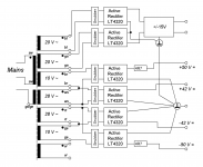
here is the schematic of the needed Powersupply (for an active Speaker) based on existing Power Stages with +/-50V for the voltage amp part and +/-42V for the VFET Powerstage. The Transformer is 750VA.
I have drawn this supply with my take of how snubbers would have to be placed and connected. So, I am looking for
1. verification of snubber placement and
2. for the correct measuring method to define values for all the snubber parts.
My guess for 2. is to short the windings I'm not measuring, with the exception of the staggered 28V/10V Windings which may have to stay open. Please let me have your advice...
Thanks and Regards,
Winfried
Attachments
")
Wgh52, the key to deciding your question is found in the title of this thread. What you want is a "Transformer Snubber" -- six of them, actually.
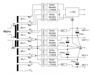
Your diagram in #1729 shows the snubbers connected across the rectifier inputs; your diagram represents an attempt to snub the rectifiers.
But that's not what you want; instead, you want to snub the transformer windings. So you reposition the snubbers in such a way that each individual transformer winding has its own snubber, as shown in the attached diagram. There are six windings and six snubbers; each snubber is connected directly across a winding.
I also show a resistor connected between the violet wires as some kind of a "termination" of the seventh winding. Personally, I simply do not care for floating wires; too many years designing CMOS might be the reason. I'd use a 1 watt resistor, whose value is chosen so it dissipates 1/4 watt in normal operation. Giving you a nice safety margin and a cool running part in a dormant piece of circuitry.
To optimize snubber number S3: make direct short-circuits across all other snubbers and across the violet wires and across the mains terminals. Every winding is shorted except ws-to-ws. Connect these two wires to Quasimodo and proceed.
Repeat another five times, individually optimizing the Rs values for the six snubbers.
Done!
_
Attachments
Hello Mark,
you cannot believe how thankful I am for your thorough analysis and the clear advice! I understand snubbing better now as well...
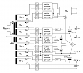
I had intentionally omitted the circuitry fed by the vi-winding, because it produces 320V= which "just" precharges a capacitive signal sensor built into the Backes&Mueller 38mm Alu-Dome-Tweeter, producing a feedback signal to control correct dome-movement. From what I learned now, this winding should get a snubber as well - IF the needed parts, my Scope and Quasimodo can handle the voltage, though. We'll see...
Thanks a lot again!
Winfried
you cannot believe how thankful I am for your thorough analysis and the clear advice! I understand snubbing better now as well...
I had intentionally omitted the circuitry fed by the vi-winding, because it produces 320V= which "just" precharges a capacitive signal sensor built into the Backes&Mueller 38mm Alu-Dome-Tweeter, producing a feedback signal to control correct dome-movement. From what I learned now, this winding should get a snubber as well - IF the needed parts, my Scope and Quasimodo can handle the voltage, though. We'll see...
Thanks a lot again!
Winfried
Last edited:


Yes. First is with all shorted.Short ALL other windings.
[off-topic-on]
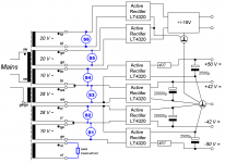
A small off-topic to avoid potential problems for readers interested in LT4320 usage:
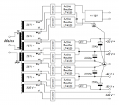
The staggering of windings voltages needs attention when using the LT4320! Staggering before rectification does not work, it has to be done after rectification! Therefore a tweaked block schematic...
Sorry for the mistake,
Winfried
[off-topic-off]
A small off-topic to avoid potential problems for readers interested in LT4320 usage:
The staggering of windings voltages needs attention when using the LT4320! Staggering before rectification does not work, it has to be done after rectification! Therefore a tweaked block schematic...
Sorry for the mistake,
Winfried
[off-topic-off]
Attachments
I want to thank the so many people that have put effort into this project – especially Mark!
I just got my Quasimodo board put together. I am using a +5V supply, a Cx of 10nf and Cs of 150nF.
I am using this on a transformer that has a 115V & 230V input. I have left the 230V input wire alone and shorted the other two together – this is the way the transformer is used.
The output of the transformer has a center tap so I have connected the center tap to one of the two other outputs and inserted these two connections into the Quasimodo board.
All seems to be working exactly as it should, but my RV1 (the pot) needs to be set to 5.3 ohms… Very low…
Just want to see if I could be doing something wrong?
Last edited:
Short ALL the primaries.
Secondary output wire to CT is what’s measured, then you put (2) snubbers on the secondary, end to CT, and the other end to the CT
Adjust potentiometer to make trace look like the bottom photo in post #1717 Simple, no-math transformer snubber using Quasimodo test-jig
Secondary output wire to CT is what’s measured, then you put (2) snubbers on the secondary, end to CT, and the other end to the CT
Adjust potentiometer to make trace look like the bottom photo in post #1717 Simple, no-math transformer snubber using Quasimodo test-jig
Last edited:
Short ALL the primaries.
Secondary output wire to CT is what’s measured, then you put (2) snubbers on the secondary, end to CT, and the other end to the CT
Adjust potentiometer to make trace look like the bottom photo in post #1717 Simple, no-math transformer snubber using Quasimodo test-jig
OK, I have shorted all primaries. Actually made no difference at all to the trace.
I am confused as to why I would connect the 230V primary connection. I live in the USA and in my setup the 230V primary connection would be just left floating?
I replaced the 1K pot with a 50 ohm pot.
I am now reading 10 ohms for a trace that looks like the one Mark showed in post #1717.
I guess my question is 10 ohms a reasonable reading?
Is there any advantage to using a power supply that is +18V compared to a +5V supply?
Thanks!
Last edited:
- Home
- Amplifiers
- Power Supplies
- Simple, no-math transformer snubber using Quasimodo test-jig