Re: J501
And that is the $64,000 observation Fred. But it gets better. The point at which the disturbance is injected is inside the feedback loop. The open-loop gain from the point of the disturbance to the output is nearly one at low audio frequencies and is less than one at higher frequencies because of the load capacitor. So the closed-loop transfer function from the disturbance to the output is Gpass/(1 + loop_gain) where Gpass < 1. There's plenty of feedback at audio frequencies so the loop gain is large. At 20 kHz you may have something like 40 dB of loop gain. So you're up to more than 140 dB of rejection, closed-loop (at least in theory). 100 dB of rejection from unregulated input to the emitter of the emitter follower, and roughly 40 dB of rejection from a disturbance at this emitter to the output proper. I can live with that 🙂 .
Fred Dieckmann said:(...)Before someone else points it out, it might be worth noting that this current source is feeding a circuit with a few ohms of output impedance. The load is the output impedance of an emitter follower and may not come close to justifying a cascode current source of several Meg for it's bias current.
And that is the $64,000 observation Fred. But it gets better. The point at which the disturbance is injected is inside the feedback loop. The open-loop gain from the point of the disturbance to the output is nearly one at low audio frequencies and is less than one at higher frequencies because of the load capacitor. So the closed-loop transfer function from the disturbance to the output is Gpass/(1 + loop_gain) where Gpass < 1. There's plenty of feedback at audio frequencies so the loop gain is large. At 20 kHz you may have something like 40 dB of loop gain. So you're up to more than 140 dB of rejection, closed-loop (at least in theory). 100 dB of rejection from unregulated input to the emitter of the emitter follower, and roughly 40 dB of rejection from a disturbance at this emitter to the output proper. I can live with that 🙂 .
Noise
Hi Jocko Homo,
What can you tell us about the noise source (amplitude, type--white, etc.)?
Also, I note that no one replied to dimitri's questions about LED noise.
I've wondered about LED noise, too. I've Google searched (using such search terms as "LED" "noise" "datasheet") and have yet to see an LED datasheet that specifies a noise level. I'm aware that LEDs are commonly used for constant current sources. And as someone noted, in another thread, if LEDs are noisey why would it have been used for the MAT03 "super low noise amplifier" circuit (MAT03 datasheet). I think that thread is here:
http://www.diyaudio.com/forums/showthread.php?s=&postid=13794&highlight=#post13794
Does anyone have noise data for LEDs? How will they compare to "low noise" voltage references? Are red LEDs better? (If nothing else the red LEDs have steeper If versus Vf curves.) Are GaAs the lowest noise?
Since we're (er...we'll you guys) are nailing down the details the current source, might as well cover the use of an LED. Don't mind learning it's a price/performance thing...
JF
Hi Jocko Homo,
What can you tell us about the noise source (amplitude, type--white, etc.)?
Also, I note that no one replied to dimitri's questions about LED noise.
dimitri said:So can be LED used as a voltage reference? Will such reference generate excess noise as compared with the couple of diodes connected in series? Does somebody have a reliable data?
I've wondered about LED noise, too. I've Google searched (using such search terms as "LED" "noise" "datasheet") and have yet to see an LED datasheet that specifies a noise level. I'm aware that LEDs are commonly used for constant current sources. And as someone noted, in another thread, if LEDs are noisey why would it have been used for the MAT03 "super low noise amplifier" circuit (MAT03 datasheet). I think that thread is here:
http://www.diyaudio.com/forums/showthread.php?s=&postid=13794&highlight=#post13794
Does anyone have noise data for LEDs? How will they compare to "low noise" voltage references? Are red LEDs better? (If nothing else the red LEDs have steeper If versus Vf curves.) Are GaAs the lowest noise?
Since we're (er...we'll you guys) are nailing down the details the current source, might as well cover the use of an LED. Don't mind learning it's a price/performance thing...
JF
Well JF, if you observe that we are already getting PSRR up to 100dB for this part of the circuit, you might have to ask yourself how much more improvement you could expect by replacing the LED with something more quiet.
An LED will have shot noise across its junction, just like any other semiconductor device. Shot noise is more pronounced at lower currents. I've also read, but never confirmed for myself, that LEDs have some photoelectric effect. I put a drop of opaque goop on LEDs used as references, to keep them from interfering with other LEDs in the same case. This may be pure crap though.
Probably better to spend time on circuit layout than poring over datasheets to find the perfect LED.
There's something about an aqua violet man
"Here is the measured performance of the circuit. Since it may be hard to read (decent pens are getting harder to find at short notice), the data is:"
Those are pretty goofy looking colors all right ........
What about the LED noise?
"Here is the measured performance of the circuit. Since it may be hard to read (decent pens are getting harder to find at short notice), the data is:"
Those are pretty goofy looking colors all right ........
What about the LED noise?
Attachments

jwb said:Well JF, if you observe that we are already getting PSRR up to 100dB for this part of the circuit, you might have to ask yourself how much more improvement you could expect by replacing the LED with something more quiet.
...
You make some points there. However, a lot of the numbers presented here are from simulation. Haven't seen actual numbers that are 100db. And I'm working on layout now (next to piles of datasheets).
And as far as the Aqua Velva: Fred, "Thanks, I needed that!"
JF

Hi,
Is this the link you mean?
DIODES
Cheers,😉
EDIT: This is the complete url:
http://ppewww.ph.gla.ac.uk/preprints/1995/06/rbates/node3.html#SECTION00012000000000000000
Is this the link you mean?
DIODES
Cheers,😉
EDIT: This is the complete url:
http://ppewww.ph.gla.ac.uk/preprints/1995/06/rbates/node3.html#SECTION00012000000000000000
Re: Jung Super Regulator, collecting the parts
Say Fred, it would be easier to contact you by email if your email was in your profile, or you accepted email from this forum's forms.
I am curious what FET you used at the output of the opamp. I too would prefer to eliminate the zener level shifter in favor of an LED.
I've noticed you don't really care to share part numbers. You even blacked out the opamp in ALW's photo (it's AD817). But I also noticed you have a preference for Japanese transistors and maybe you'd like to share. I have managed to put together a reasonable pile of good Japanese transistors from disassembling older computer power supplies.
Fred Dieckmann said:I have finished the positive regulator using the kit I got from ALW. I made few changes that seemed good ideas in theory [...] the driver between the output BJT and the op amp is a low capacitance mosfet. The mosfet is a very high impedance for the op amp to drive at audio frequencies...
Say Fred, it would be easier to contact you by email if your email was in your profile, or you accepted email from this forum's forms.
I am curious what FET you used at the output of the opamp. I too would prefer to eliminate the zener level shifter in favor of an LED.
I've noticed you don't really care to share part numbers. You even blacked out the opamp in ALW's photo (it's AD817). But I also noticed you have a preference for Japanese transistors and maybe you'd like to share. I have managed to put together a reasonable pile of good Japanese transistors from disassembling older computer power supplies.
Another pass element transfer function plot...
Just for grins, I though I'd do another plot of the voltage transfer function of the pass elements of the 90 Volt regulator I posted here: http://www.diyaudio.com/forums/show...6528#post256528. I wanted to show the variation with load current and frequency. This plot is from the base of the PNP emitter follower connected to the op-amp output to the overall output of the regulator. Since the open-loop output impedance of the pass element is roughly inversely proportional to DC load current, you'd expect less and less attenuation at the series resonant frequency of the load capacitor (about 93 kHz) as the current goes up. And that's just what is seen in the plot. This plot steps the current from 20 mA to 200 mA in 20 mA steps. The highest attenuation and greatest phase variation with frequency are for the lowest current, with the opposite effect for the highest currents. This clearly shows that the stability of the circuit depends on DC load current. Also, one should not depend on getting a whole lot of high-frequency attenuation out of the load capacitor - certainly not more than a few dB if the current is at all high.
A couple of the phase traces are a very pale red and purple and almost invisible. Also, the colors for the phase plot unfortunately aren't the same as those for the magnitude plot at the same current. This appears to be a minor bug in LTSpice.
Attachments
Nice work but the ground around the reference seems 
The ground at the connectors can be improved I think. I think you have missed the "ground sense" concept. You must not connect them internally and if you want that you must do it with some resistor+cap. Do you use groundplane? If not I recommend that you do.
The ground at the connectors can be improved I think. I think you have missed the "ground sense" concept. You must not connect them internally and if you want that you must do it with some resistor+cap. Do you use groundplane? If not I recommend that you do.
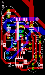
i didn't put the ground plane in yet -- it makes it harder to see the silk when you screen-capture the image.
i will move/reverse the GND_OUT and GND_SENSE and connection to the "star blob", that's a good point.
the compromise -- in Walt's article he uses a "hole" or "pin" for the connections. I have chosen to use MKDS15_2RMI and MKDS15_6RMI connectors.
btw, I saved the entire thread and copied it to a PDF unexpurgated -- it's an entire meg, but if anyone wants one email me.
Here's my take. This layout is for a regulator whose load is adjacent, so it doesn't have any wire connectors. Sorry none of the parts are marked, it's a bad CAD package. Q17 is the pass element, the current source is on the left, and the reference is on the right. This is the "Improved Improved" regulator with current-setting resistors replaced with JFET current diodes.
Attachments
Boss de Plane de Plane!
" here's a first cut:"
And here's the next one, rotate the output transistor from 9 o'clock to noon. The emitter lead is the least important one to have long since it's resistance is inside the feedback loop. Put a base resistor right at the base of the output transistor and keep the base and collector traces short. This is a high bandwith circuit. The single point grounds don't need a big fill or does the output. Let the feedback and sense traces do their job and don't worry about fat traces that are inside the feedback loop. Your ground sense line isn't and needs a jumper for using either local ground are the sense lead to the load. I am really curious why you left out AWLs enhancements which are worthwhile. Think current paths and the tightest layout you can get. I would not bother with a ground plane on a circuit this small and a two layer board which puts the plane 0.065 from the traces. Use some guard traces around the feedback network and return them to the ground pin of the op amp if you nervous without the plane. There is much much more to this layout than meets the eye as Jan and Andy and perhaps even Mr. Jung will tell you. I don't want to speak for Walt, but Andy and Jan have weighed in on this several times. You don't need the clamp diodes with the 825 and theyare taking up room in the most critical part of the layout!
One immediate reaction to jackinni's post was to move the connection from the V+_unreg to the collector of the pass transistor. Doesn't make sense to run the entire load current around the board and generating false voltages between the other points connected to this trace.
Other than that, I agree largely with Fred.
Jan Didden
Other than that, I agree largely with Fred.
Jan Didden
Here is my implementation of the regulator.
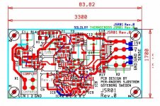
The green traces are connections to the groundplane, not shown. I have made room for three different kinds of references, TO92, SOT23 and SO08. It is also a negative regulator in the same pcb. The Wago connectors are huge compared to the other parts. If I ever will make a pcb I probably have 50 or 95 um copper (35 um or 70 base material + 25 um plated).
If someone want to think something, I have a minor "error". The sense ground isn't 100 % perfect but 10 mm 95 um copper won't create so much voltage drop of some uA's. It's around IC3, C6 and R8
Attachments
These references are for flexibility. Of course, only ONE at the time.Fred Dieckmann said:BTW How are all those voltage references in parallel working out? I wonder how you insure that the current is shared equally and put the outputs of the amplifiers that they contain in parallel without decoupling and still maintain stability? That's something that I don't understand.
BTW: Is there any similar reference like the LM129 but in SOT23 or SO08? = good reference which is not heated. As I gathered LM129 is an unheated LM199/399.
- Home
- Amplifiers
- Power Supplies
- Super Regulator, collecting the facts