R4 full clockwise to zero and no success. Not any mA. reading.
I have breadboard, but I am afraid lacking knoleadge to do so.
Attachments
What happens if R4 has full value? Is there also a possibility there happened a discontinuity in the CCS circuit?R4 full clockwise to zero and no success. Not any mA. reading.
I have breadboard, but I am afraid lacking knoleadge to do so.
Hola Felipe, remove zeners makes no difference on this high powerful IXYS, neither dialing up the trimmer R4.
On swapping differents DN2540, I manage to increase the cascode performance to 130mA. Still far away from my needs, so now I am going to buy some assorted IXYS among less powerful ones.
IXTP01N100D and IXTP02N50P in particular looking good, as are featuring:
• Low RDS(on) HDMOSTM Process
• Rugged Polysilicon Gate Cell Structure
• Fast Switching Speed
Very different from the remaining most powerfull IXYS lineup, which instead feature: intended for Audio Amplifiers.
IXTP08N100D2 you mean? Has been reported working well instead of DN2540 in CCS applications.
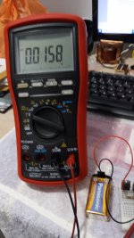
Today I tried again, this time using the CCS isolation trick, tying F+ to F0 and leaving the S terminals open, then powering with a 9v battery.
IXTH6N50D2 has same odd beavior as in HV environment, no Vgs readings. Otherwise it looks healthy, my multimeter is able to open and close the door.
I'll give a break, it won't take long to receive new, more suitable parts.
Felipe, what symbol refers to Shunt Capacitance to see it in the Pdf file? This specification may have grater impact on any of two Dmos cascode CCS?
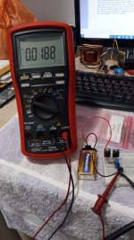
Seems like it doesn't get triggered at all in this scheme that 300W DMOS. Needs much current to develop a bit of Vgs. Or it doesn't fit well and misses a connection.Today I tried again, this time using the CCS isolation trick, tying F+ to F0 and leaving the S terminals open, then powering with a 9v battery.
IXTH6N50D2 has same odd beavior as in HV environment, no Vgs readings. Otherwise it looks healthy, my multimeter is able to open and close the door.
I'll give a break, it won't take long to receive new, more suitable parts.
Felipe, what symbol refers to Shunt Capacitance to see it in the Pdf file? This specification may have grater impact on any of two Dmos cascode CCS?
*Better use two 9V batteries in series for 18V LV CCS test because nearer to real life parasitic capacitance and Idss as this circuit is usually applied.
**The way you now test with the FF shorted trick and extension pins you practically breadboard. But on FR4 material.
**The way you now test with the FF shorted trick and extension pins you practically breadboard. But on FR4 material.
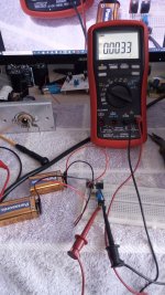
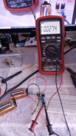
Done in mine breadboard with two cascode IXTP01N100D to help Jordi pics showing min. & max. current, the resistors used to measure the CCS current is 1R so min. 3.3mA & max. 27.4mA*Better use two 9V batteries in series for 18V LV CCS test because nearer to real life parasitic capacitance and Idss as this circuit is usually applied.
**The way you now test with the FF shorted trick and extension pins you practically breadboard. But on FR4 material.
Attachments
Last edited:
I have received IXYS, but noticed that perform worse current capability.
At same R1 R2 = 100R:
DN2540 can reach 134mA.
IXTP02N50P reach 100mA.
IXTP01N100D far less, 42mA.
Is Ok. 360R resistor value in the transiator gates? I can measure the performance in my oscilloscope, but very limited experience using it, I am afraid I will need assistance. By now the multimeter reading is stable. I wants also implement IXYS ones.
Last edited:
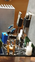
First try on IXYS is sucessful, but I doubt can set them this way because D2 burns at touch after half minute. Time enough to take this measurements based on settings: R1,R2=360R @ 170mA @77Vout.
DN2540 ==> R4(R3)=7,6R and 90VDC in
IXTP02N50P ==> R4 =7,2R and 95VDC in
IXTP01N100D ==> R4=0R and 108VDC in.
DN2540 ==> R4(R3)=7,6R and 90VDC in
IXTP02N50P ==> R4 =7,2R and 95VDC in
IXTP01N100D ==> R4=0R and 108VDC in.
- Home
- Amplifiers
- Power Supplies
- Simplistic MosFET HV Shunt Regs