Transformer calculations
CV - GREAT post! That was exactly the kind of information I needed to get me started.
Based on plugging in parameters from my torroids I can see that they have the (probably fatal) flaw of too small a cross section. A very rough calculation says that my F-150-W core has a cross section of ~ .257 CM^2 as compared to the 2 CM^2 in your assumption. Working this through seems to indicate that it is too small to handle the kind of input voltages I need to reasonably power the ribbon.
As luck would have it, I ordered two additional cores yesterday AM when I ordered the new magnet wire and they look like they could work very well.
Here are the calculations for these new toroids and where I use other formulas from the net, I'll post a reference link.
------------------------------------------------------------------------------
New torroids:
Model FT240-77 (2.4" OD, 1.4" ID, .5" thick - Type 77 ferrite)
http://www.oselectronics.com/ose_p88.htm
u = 1800
mh/1000 turns = 2740
Max flux density of type 77 = .46 tesla
------------------------------------------------------------------------------
Here we go:
----------------------------------------------------------------------
CALCULATE DESIRED PRIMARY INDUCTANCE
-----------------------------------------------------------------------
Primary Reactance = "CV" Rule of thumb 5-10 times desired impedance
Xl = 2Pi * f* L
http://www.allaboutcircuits.com/vol_2/chpt_3/2.html
L = XL / (2Pi * f)
L = 8 * 10 /(6.28 * 1000)
L = .0127 ~ 13 mh
Xl = desired impedance in ohms
2Pi = 6.28......
f = crossover frequency = 1000hz
L = inductance in Henry
__________________________________________
CALCULATE PRIMARY AND SECONDARY TURNS
------------------------------------------------------------------
Primary Turns = 1000 SQRT (L / toroid mh per 1000 turn)
http://www.oselectronics.com/ose_p88.htm
L = Primary Inductance in mh
Primary Turns = 1000 SQRT (13 / 2740)
Primary Turns = 68 Turns
Primary impedance = Turn Ratio ^2 * Ribbon resistance
Turns Ratio = SQRT (Primary impedance / Ribbon resistance)
Turns Ratio = SQRT (8/.028) = ~16
------------------------------------------------
Secondary Turns = Primary Turns / Turns Ratio
Secondary Turns = 68 / 16 ~ 5 Turns (rounded up)
-------------------------------------------------------------------------
CALCULATE MAXIMUM INPUT VOLTAGE AND POWER
------------------------------------------------------------------------
A = Torroid Cros Section = 1.25cm *1.25 cm = 1.56 cm ^ 2
A = .000156m^2
-----------------------------------
N = V / (4 * F * A * B)
(Formula different than CVs but mostly units and maybe CV forgot Frequency term?)
http://www.magmet.com/lamination/europeantransformer.html
N = Primary Turns
V = Max RMS Primary Voltage
F = Xover Frequency
A = Torroid cross section in M^2
B = Max flux denisty in torroid in Teslas
4 = constant (something to do with converting peak V to rms?)
V = N * 4* F * A * B
V = 68 * 4 * 1000 * .000156 * .46 = 19.5 V rms
-------------------------
P = V^2 / R
P = 19.5 ^2 / 8 = 47 watts
P = Max power applied to primary without saturating core
R = Reflected impedance at primary
----------------------------------------------------------------------------
SUMMARY FOR FT240-77 BASED RIBBON TRANSFORMER
----------------------------------------------------------------------------
Primary = 68 turns (I'll probably use 16AWG wire)
Seconday = 5 turns (I'll use 14 AWG wire)
Impedance @ Primary = 8 ohms
Max power at Primary = 47 watt (more than enough)
--------------------------------------------------------------------------
I hope I didn't botch the math too badly. Let me know if I did. I got a feeling I'm going to be using the edit button on this one.
Denis
Joules said:dhenryp - How do you cut the aluminum and how do you keep the ribbon straight wile rolling the waves in to it? How much tension do you put on the ribbon when you install it between the magnets.
keep up the great work - we'er all behind you 200%
I just put the foil on a flat surface then put a straight edge on top of the foil. Use a sharp/new razor blade and hold the blade at a low angle to the surface. Press firmly and cut slowly. It's not too hard to get clean 8-9 inch strips, at least with the thickness of foil I use.
I haven't got the "straight waves" part down yet. Mine tend to drift in one direction or another. Maybe practice will make perfect. I think if you get it right to the first order, everything else is cosmetic.
Hi Joules,
To add to Denis's input, I use a piece of flat glass and wet the foil lightly with water so it holds down. I use a straight edge made of hard plastic or well finished metal. A metal ruler is generally too rough. Use the single edged razor blades that they sell at paint stores and like Denis says hold them at a low angle. Go slowly. Change blades often.
Graeme
Other thing that affect sound quality?
Assume I can eventually get the right size and type core and calculate the windings so that the impedances, inductances are OK and the thing can transfer power to the ribbon (big assumption).
What other properties of the transformer core and/or winding technique that will influence distortion, phase issues or other aspects of sound quality?
E.G. Is it best to put primary on one part of the core and secondary on the opposite side (assuming there is room for both with one layer) or is it best to lay the Secondary on top of the Primary?
Electra-print audio ( www.electra-print.com ) seem to specialize in audio transformers with "wa-zoo" core material for line level xformers and out put xformers. Maybe they might be of some help.
Maybe replacement ribbons for the Raven's or others ribbons tweeters are available, I understand they are relitivly inexpensive and might be easer to setup and use in your Device. ... maybe ...I think ...
Maybe replacement ribbons for the Raven's or others ribbons tweeters are available, I understand they are relitivly inexpensive and might be easer to setup and use in your Device. ... maybe ...I think ...
tiroth said:Repost of Talema data from my samples. I can send you a 35VA unit if you want to experiment. Maybe the leakage inductance is too high though. The smaller cores are way better on this measurement.
I looked at the Digikey site and could not find the Talema transformer. Can you give me a pointer. When I find the data sheet and understand how I could use it I will take you up on yourkind offer of a sample.
Thanks!
Denis
LineSource said:I have built amps that can direct drive 0.1 ohm Apogee ribbons and was not happy with the sound. I then converted to a 5.8 micron ribbon that increase the restance to 0.35 ohms, tripled efficiency, and it sounded wonderful with the direct drive amp. Much better than with a transformer.
LineSource - Can you point me to a source for 5.8 micron aluminium? The 12 micron stuff I'm using is the thinest I've been able to find.
Thanks,
Denis
Joules said:Electra-print audio ( www.electra-print.com ) seem to specialize in audio transformers with "wa-zoo" core material for line level xformers and out put xformers. Maybe they might be of some help.
Maybe replacement ribbons for the Raven's or others ribbons tweeters are available, I understand they are relitivly inexpensive and might be easer to setup and use in your Device. ... maybe ...I think ...
I looked at the Electra-print page and it looks like these are for vacuum tubes. I think these are quite different from the point of view of the impedances they match, the current they drive to the output and the voltages involved. I could be wrong, but they don't look like they transfer to ribbons (plus they look expensive).
I have seen a guy inthe UK that sells matching Xformers for an old ribbon (Decca?) that is quite reasonable ($60-70 ?). I'm inclined to move forward with a DIY design because:
1. It's interesting (at least to me)
2. buying a pre-built might work, but it might not and I might never understand what the problem was.
3. There is at least the potential to come up with a design that matches my situation better.
4. There is also the potential to come up with a cheaper Xformer, although at the rate I'm going I will end up spending MORE money. Maybe it will help the next person making a DIY ribbon.
Thanks for the suggestions and the encouragement!
Denis
The Talema/Amveco potted toroids are items TE70000 and up.
The TE70000 - TE70005 are dual 7V up to dual 22V, 1.6VA. There are six part numbers per decade, so this same naming convention continues with TE70085 being the largest (50VA) potted toroid.
The "mini" transformers use the same convention and the part numbers are TE62000 and up.
It helps to have a catalog, Digikey sells all sorts of stuff you'd never find on their site.")
The TE70000 - TE70005 are dual 7V up to dual 22V, 1.6VA. There are six part numbers per decade, so this same naming convention continues with TE70085 being the largest (50VA) potted toroid.
The "mini" transformers use the same convention and the part numbers are TE62000 and up.
It helps to have a catalog, Digikey sells all sorts of stuff you'd never find on their site.
omission from transformer eqn explanations
Allo,
My original formula, V=BANw was rougly correct but I neglected to mention what "w" was - it's the so- called "angular freqeuncy", which is just 2*pi*f.
My V is Vpk, divide by 1.414 to get the rms - if you apply these factors, you pretty much get:
N = V / (4 * F * A * B)
Actually, I think I get a factor of 4.44 there - I may have forgotten a scaling factor of 1.1 - that may have been if you use a square wave instead of a sinewave, 'fraid I can't remember.
In any case, be conservative and run the transformer with plenty of magnetic (flux limit) headroom.
I would concur that if a suitable mains toroid can be found, it may be a nice cheap option.They can have ridiculously good topend bandwidth Only thing to watch is the DCR of the secondary - don't want to throw away a load of efficiency.
Anyway, best of luck - doesn't sound like you'll need it as you seem to be well on track.
Cheers
Nothing new built or tested, but I was able to dig up some good tranformer references and answers to some of my previous questions.
First the references:
Rod Elliot and his ESP site has a two part discussion on transformer design. I love that guy; he is one of the best DIY resources on the web. It's mostly about power supply transformers but there is enough about Audio and audio frequency losses to be very interesting:
http://sound.westhost.com/xfmr.htm
http://sound.westhost.com/xfmr2.htm
Other good references:
http://www.fair-rite.com/Broadband.pdf
http://geek.scorpiorising.ca/windingtransformers.html
Regarding my question about things that could affect transformer audio quality;
It seems that the key thing to avoid distortion is to avoid running into saturation of the core (as CV said). Even though my calculation showed the transformer could handle 46 watts, I'll probably need to keep well below, maybe 30 watts, to avoid the saturation "knee" of the BH curve.
Two things that can affect phase response and high frequency response are parasitic losses due to stray capcitance between windings and leakage inductance caused by imperfect coupling of the coil field to the core.
To reduce capacitance it seems that I want to keep as much distance between the turns as possible. In other words, rather than having the turns touching each other in the toroid "hole", I should spread them out. It also seems to me that I definitely don't want to layer the secondary on top of the primary. The further apart the wires, the less capacitance between them (?).
For inductance losses, I obviously want to wind the wire as tight to the core as possible for the best coupling (but not so tight as to breake or rub off the insulation!). I THINK I also want the primary inductance (and hence the number of turns) to be as small as possible while still meeting the rule of thumb of presenting an inductive impedance at Xover 5-10 times reflected load (i.e. 8 ohm * 5 or 10). You can't reduce the number of turns too much though, because it is directly proportional to the power handling capability.
Lastly, I think I understand why my Version 1 transformer worked without blowing up my amp. The turns ratio was way too low so the reflected load was probably less than an ohm. The saving grace was that the 20uf low pass filter combined with the low impedance to produce a really high Xover frequency, maybe over 10k. There was so little power in that freqency range, especially listening to FM on a 30 year old receiver, that id didn't hurt the amp.
If anything (or everything) I said is wrong, please let me know. I'm just trying to paw my way through all the information and learn something. I hope you folks don't mind me treating this thread as kind of a Blog of my investigation. It's the kind of thread I would have liked to find when I started looking at DIY ribbons.
Denis
LineSource said:Hi dhenryp,
I can mail you some 0.7" wide 5.8 micron pure aluminum foil if you want to experiment. Just enable email on your user profile so I can get your home address.
Done and Thanks!
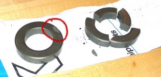
Well I got my new toroids today. One of them came with a big chip in it;and that was the good news. The other one came in four pieces It was a combination of brittle ferrite, poor packing and UPS' gentle handling.
I took the chipped torroid and made the Version 2 transformer. This wooks much better. It gives me an impedance of just about eight ohms. I've got jury rigged small gauge wiring and a couple of clip on connectors so I think I'm losing some efficiency on the ribbon side and effectively increasing its resistance with bad connections. The end result is that I got my eight ohms but only needed a turns ratio of ~ 8:1 (instead of my calculated 16:1). The primary inductance is 10mh and the leakage inductance (measured with an LRC meter and the secondary shorted) was .5mh. I don't know if this is good or not
I got out my signal generator and and did some rough efficiency measurements. With 2.88v across the transformer primary I got ~85 - 87 db output (measured with my RS meter). I'm not sure how accurate this is but it seems in the ballpark, if a little low. Maybe it will improve when I get better ribbon connections and do a better job with the winding. The 5 micron aluminum foil that linesource is sending could also increase efficiency by several db.
I can easily hit 100db from ~2k on up without obvious distortion on sine waves. I can probably go higher but have not gotten to it yet. Even the testing I've done so far has forced me to get out ear protection. Lucky I don't have a dog.
Denis
It was a combination of brittle ferrite, poor packing and UPS' gentle handling.I took the chipped torroid and made the Version 2 transformer. This wooks much better. It gives me an impedance of just about eight ohms. I've got jury rigged small gauge wiring and a couple of clip on connectors so I think I'm losing some efficiency on the ribbon side and effectively increasing its resistance with bad connections. The end result is that I got my eight ohms but only needed a turns ratio of ~ 8:1 (instead of my calculated 16:1). The primary inductance is 10mh and the leakage inductance (measured with an LRC meter and the secondary shorted) was .5mh. I don't know if this is good or not
I got out my signal generator and and did some rough efficiency measurements. With 2.88v across the transformer primary I got ~85 - 87 db output (measured with my RS meter). I'm not sure how accurate this is but it seems in the ballpark, if a little low. Maybe it will improve when I get better ribbon connections and do a better job with the winding. The 5 micron aluminum foil that linesource is sending could also increase efficiency by several db.
I can easily hit 100db from ~2k on up without obvious distortion on sine waves. I can probably go higher but have not gotten to it yet. Even the testing I've done so far has forced me to get out ear protection. Lucky I don't have a dog.
Denis
Attachments
Hey dhenryp how goes the transformer ?
You have been a great insperation to me with this project. You have made it look very doable. I hope you don't mind but I think I'm going to follow in your foot steps and try and build a couple ribbons for my self. I have a small machine shop and was thinking of getting a little fancier with the pole pieces. I was thinking of using iron pipe and cutting it to resemble the ALIAN BEEngineering ribbon tweeters. It would be nice to do a little magnetic modling tho. What software did you use, FEMM? where did you get it?
The hardest part to this hole project seems to be the X-former. so I am very curious to see how yours turns out.
femm is great FREE 2-D magnetic modeling software that you can download for free here:
http://femm.foster-miller.net/cgi-bin/efileman/efileman.cgi
I don't mid at all if you make your own ribbon. That's the reason I posted this thread; to share what I'm able to come up with.
I played around withthe transformer last night and I'm quite happy with what I have now. I think a key to using the transformer is a steep enough high pass filter. I started out with a simple capacitor for a first order filter. I think the 6db slope is too shallow so that the low frequency that gets through at high volumes is enough to saturate the core, causing distortion. Last night I built a simple 2cnd order filter using components I had on hand: 14.4 uf cap and 1.2 mh coil. This gives me ~ 1k Xover frequency. With this I can play the ribbon louder than I can stand to listen too (within 10 ft) with no obvious distortion. When I build my final version for my line array I will probably go with a 4th order LR active Xover so it should work even better.
The next things I'm going to work on are:
1. I'm going to increase the gap to .75". Femm says I should still get ~.42 Tesla in the gap so I don't expect efficiency to suffer. This will also allow me to easily experiment with the .7" foil linesource is sending (thanks!).
2. I've order all the steel and magnets to build two of the final line source ribbons. They are going to be ~48" tall with the net powered ribbon length being ~ 36" long.
3. I need to get my justmls measuring system set up. I just got a new computer so I will be using my old computer as a dedicated measuring system. This may take a little time, but I realize it's critical because up until now, most everything I've reported is subjective.
Regards,
Denis
The problem with wider gaps in ribbon drivers is not the field strength, it's the uniformity of the flux across the width of the ribbon. The edges of the ribbon will driver harder than the center. To an extent the corrugations will lend a bit of mechanical strength so that the middle is dragged along by the edges. There's a limit to how far you can take this, however, elseways everyone would be making 2" wide ribbons and we'd be able to get down into the 100's of Hertz before going over to another type of driver.
If you haven't already, try modelling the driver looking down its length.
Yes, stronger magnets help. Good luck.
Grey
If you haven't already, try modelling the driver looking down its length.
Yes, stronger magnets help. Good luck.
Grey
Multiflar Tranformer Winding
I've been doing some reading on the web about how to reduce parasitic transformer losses. With the realtively small number of turns on a Ribbon matching transformer, it appears that capaciatnce between turns is not important - it's a different storry if you a build a vacuum tube output transformer with thousands of turns. Wire resistance losses are handled by using big wire.
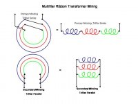
The most significant loss for my application is leakage inductance. You can meaure it by shorting the secondary and measure the inductance across the primary. This leakage inductance can limit high frequency response and also can cause high frequency phase changes. This can be reduced a lot by using bifilar, trifilar, .... - generically called multifilar winding. For bifilar winding, you take two pieces of wire, twirl them together (not tightly) and then you wrap the pair around the toroid. Since you have two wires, you wrap the pair half the number of turns you've calculated (times two wires for each turn gives the correct number of turns). You have to connect the two primary wires in series in order to have the right number of turns. It's hard to describe in words so I've attached a diagram to show how it is wired for a three wire case (trifilar). This gives you a more efficient coil. It's not intuitive to me why it works but I think it was first invented by Tesla (yes, THAT Tesla)
In the test I've done, I compared a standard wired toroid (one wire primary with a single wire seconday wrapped over it) to a toroid wired per the picture. They both had the equivalence of 30 primary turns and 5 secondary turns. I wired the primary in series trifilar. I think this has the most effect on leakage inductance. I wired the seconday with three wires in parallel. I think this mostly helps current carrying although it also has an affect on leakage. (I've not seen the terms "series" and "parallel" applied to these windings but it makes sense to me so I'm going to use it here).
The bottom line; The bifilar wound transformer had leakage inductance about 1/3 of the standard windings. The standard transformer had leakage inductance ~ .5 mh and the bifilar was ~.16 mh. The primary inductance was slightly higher for the bifilar transformer (~5-10%) and the secondary inductance was unchanged. I also tried as high as hexfilar (6) primary windings with the primary and secondary twirled together (for maximum coupling). This made very little improvement (probably within my measurement accuracy).
For my ribbon, I'm going to use 18 awg trifilar primary winding and probaly 20 awg quadfilar winding for the secondary.
I've been doing some reading on the web about how to reduce parasitic transformer losses. With the realtively small number of turns on a Ribbon matching transformer, it appears that capaciatnce between turns is not important - it's a different storry if you a build a vacuum tube output transformer with thousands of turns. Wire resistance losses are handled by using big wire.
The most significant loss for my application is leakage inductance. You can meaure it by shorting the secondary and measure the inductance across the primary. This leakage inductance can limit high frequency response and also can cause high frequency phase changes. This can be reduced a lot by using bifilar, trifilar, .... - generically called multifilar winding. For bifilar winding, you take two pieces of wire, twirl them together (not tightly) and then you wrap the pair around the toroid. Since you have two wires, you wrap the pair half the number of turns you've calculated (times two wires for each turn gives the correct number of turns). You have to connect the two primary wires in series in order to have the right number of turns. It's hard to describe in words so I've attached a diagram to show how it is wired for a three wire case (trifilar). This gives you a more efficient coil. It's not intuitive to me why it works but I think it was first invented by Tesla (yes, THAT Tesla)
In the test I've done, I compared a standard wired toroid (one wire primary with a single wire seconday wrapped over it) to a toroid wired per the picture. They both had the equivalence of 30 primary turns and 5 secondary turns. I wired the primary in series trifilar. I think this has the most effect on leakage inductance. I wired the seconday with three wires in parallel. I think this mostly helps current carrying although it also has an affect on leakage. (I've not seen the terms "series" and "parallel" applied to these windings but it makes sense to me so I'm going to use it here).
The bottom line; The bifilar wound transformer had leakage inductance about 1/3 of the standard windings. The standard transformer had leakage inductance ~ .5 mh and the bifilar was ~.16 mh. The primary inductance was slightly higher for the bifilar transformer (~5-10%) and the secondary inductance was unchanged. I also tried as high as hexfilar (6) primary windings with the primary and secondary twirled together (for maximum coupling). This made very little improvement (probably within my measurement accuracy).
For my ribbon, I'm going to use 18 awg trifilar primary winding and probaly 20 awg quadfilar winding for the secondary.
Attachments
If 1 inch of corrogated ribbon requires 1.3 inches of aluminum length in the flat, or there abouts, then,
--------------------------Alum Aly--------1100 ----------- 5052
------------------------------------------2.9x10^-6-------4.9x10^-6
-----------------------------------------uohm cm3--------uohm cm3
----------------------------------------------V-------------------V
6.3 micron (.00025") x .25wide = .096 ohms -------.162 ohms
10 micron (.0003937) x .25wide = .061 ohms --------.103 ohms
6.3 micron(.00025inch) x.25wide-----4ohms = 41.66 inches long
-------------------------------------------8ohms = 83.33 inches long
10 micron(.000393inch) x .25wide----4ohms = 65.67 inches long
-------------------------------------------8ohms = 131.14 inches long
www.allfoils.com/products_aluminum_foil.html
- Status
- This old topic is closed. If you want to reopen this topic, contact a moderator using the "Report Post" button.
- Home
- Loudspeakers
- Planars & Exotics
- Another DIY Ribbon thread