exactly and yes..if it has separate attenuators for each channel that will work.
With some more cheap work you can get them running with the original crossover board outside of the main speaker cabinet so you can make adjustments and testing much easier. It does not cost much but safety and appearance both fall since there is 120volts on the transformer feeding the high voltage.
It really is the only way to modify them though since removing the woofers just to change a capacitor value is a PITA. It can be done without any permanant alterations to the original cabinet.
for the woofer amp remember it should really be called a woofer/midrange amp so I would consider an amp the will compliment what you use for the upper range.
The internal woofer xover on mine is 18dB at roughly 250hz so there is enough mid range that I would want to use a decent amp.
I guess I tend to think of plate amps for subwoofer rather than woofer.
The internal woofer xover on mine is 18dB at roughly 250hz so there is enough mid range that I would want to use a decent amp.
I guess I tend to think of plate amps for subwoofer rather than woofer.
running with the original crossover board outside of the main speaker cabinet
I'll have to disassemble one, but I think the crossover and bias supply are in the speaker middle mounted to a bulkhead above the woofer and below the electrostatic element. Pulling it out will be a PITA, but as you point out, changing one thing and then the next is even worse if one has to go through disassembly each time.
I'll keep my eye out for an OK amplifier with a similar sensitivity, and I'll also check to see what woofer is being used. I've no idea what the original one was, though, so it may be more of academic interest. And yes, 250 Hz is about middle C on the piano, so that is midrange. Bass for me starts at or about the piano wound strings, which is an octave lower. But I won't quibble too much about nomenclature here.
Get a chance to dig into the crossovers and woofers?
Did whoever replaced the woofers on yours put all the original stuffing back in?
For reference mine has a 2" foam circle pushed up into the top of the chamber
and dacron fluff filling the rest of the space.
For running the xover/HV supply outside the enclosure I used 10kv test probe wire from the top 3 position terminal strip down the back of the cabinets. The round black top remained off.
I zip tied the original panel wires so they did not fall down the lense hole.
I think I should install a separate metal box for the xover to remain outside the main
enclosure, or maybe just the HV supply and 120v.
The acoustic foam is pushed up against the crossover board and the HV board power transformer is right there screwed to the mdf. If it ever fails it might be a fire issue.
Sorry I can't help with your Model 5's.
I do have a pair of Model 3's and have heard Model 2's- they definitely don't sound the way you describe.
In fact some people that have heard mine believe they are some of the most transparent and dynamic electrostatics they ever heard-- add into the mix their ability to hang a image in air-- and you have quite a unique experience
All the the Bev model 3 and Model 5 crossovers and step up networks are the same electrically from what I can discern. Of course your speakers have the FR board stators while some of the Model 5's have the cast stators like my 3's and 2's.
I hope you can find your issue regarding your experience of diffuse sound. Phase or perhaps step up voltage and certainly your caps in the crossover- even if the measure well could contribute. I would rebuild the step up network and the cross over. Don't underestimate your need for a very stable high quality amp as the capacitance of the panels can cause havoc with some lesser quality amps.
As to the aluminum film... I hope you find a solution. I would be interested if any commercial or semi- commercial restorers would take this on if they are watching this thread. Luckily my mylar is , knock on wood, in great shape. I don't have the patience or skill for the rebuilding of a panel- I stick to the electronics. Finding someone other than Rick Beveridge who could do it would be great.
I spoke to Roger Modjeski a few years ago and he said he might take something like that on once his new shop was set up-- worth a try.
My Bev's have been modified with direct drive amps and I am having an absolute blast with them. I have them first order crossed to a pair of stereo subs right at the direct drive amp's input with a high quality teflon film cap.
Good luck with your project.
I have contacted the Shackman-Reromanus guys, they can repair the panels but can not provide any replacement panels:
> leider haben wir keine Ersatzpanele für die genannten Typen.
>
> Wir können die Panele also nur reparieren.
>
> Best Grüße
>
> reromanus team
> Römer
> Shackman_reromanus_roemer-audio
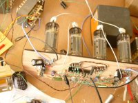
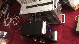
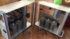
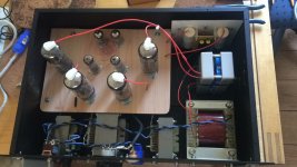
I have rebuilt the amps for my 2 Beveridge II sets (one with SW and 1 without)
> leider haben wir keine Ersatzpanele für die genannten Typen.
>
> Wir können die Panele also nur reparieren.
>
> Best Grüße
>
> reromanus team
> Römer
> Shackman_reromanus_roemer-audio
I have rebuilt the amps for my 2 Beveridge II sets (one with SW and 1 without)
Attachments
Last edited:
I have never dealt with them as well just inquired as i also need to repair one of the loudspeakers.
BTW the stators of the speakers are highly resistive (instead of the foil) that is why there will be no distortion as has been mentioned earlier.
My guess is that anyone who has experience in building ESL's could rebuild some panels. Most importantly is here that the panels must be able to produce the levels that are needed (like Acoustat or Audiostatics) if these are full range.
I do not think Herr Römer is the best address for Bevridge repairs. I have read/heard about problems dealing with him.
Yes,
I don't know what the skill is of Romer, however, there is at least one vocal past customer who says he did not repair the panels properly.
Beveridge repair by Reromanus SUCKS !, Lautsprecher und Subwoofer - HIFI-FORUM
No, I won't get to it until the weekend. I'm still gathering materials, such as a table for the measurement equipment/computer and sawhorses to lay the speakers on their side. I'll be at this for a while, and it makes sense to minimize the grief!
rebuilding Bevs
Hello:I have owned Bevs (2sw)years ago and heard all the later models before they went out of business. The bass end was never that good in any of the models but the mids and highs were spectacular in their wall of sound and holographic presentation. After trying several other ESL's I decided to build my own Bev equivalents. After experimenting for 2 years with lens designs and Xover points I finally was able to produce a speaker with similar characteristics. Using a more standard stator design with non aluminized mylar (6 or12um with transformers and a good quality stable amplifier works well. and avoids some of the safety risk of aluminized mylar. It is much easier to get also. Since I have built these speakers from scratch it is possible I can be helpful. I am located just south of Portland OR. So if you are near and wish to see what can be done using the Beveridge lens principle but changing the way the rest of the system works it may be helpful in rebuilding your speakers.
regards
Has anyone here rebuilt Beveridge circuit board electrodes/stators? I'd like to know what I would be getting into before I start.
I've always been fascinated with Beveridge ESLs -- in pristine shape, to me they sound compelling. Technically they are a clever series of trade-offs. I think they can be made to sound better with a different set of trade-offs. I'd like to try.
So I bought a pair of Model 5s -- their lowest end model -- that were available locally for a very reasonable price. I'm still assessing what I have and what needs to be fixed. To those not familiar with the Beveridge line, the Model Five is a five foot tall, 18" diameter cylinder that contains a 3'x1' electrostatic element and a 10" woofer. The ESL front wave passes through an acoustic lens (waveguide); the rear wave is damped. The woofer is downward facing, and occupies the lower 2' of the enclosure. The crossover is at about 150 Hz.
This pair dates from 1984, and has had some attention paid to it over the years. There is non-crumbing grille foam, and the woofers work, so they either have been replaced or had the surrounds repaired.
The electrode/stators show quite some loss of aluminum from the diaphragm, mostly down the center line. Interestingly, the capacitance values are not that far off from what was written on the panel edges. They do work, but are very old, and probably should be refurbished before I do much else.
I've scoured the web, and find little information on the Beveridge circuit board electrodes other than that they are notoriously unreliable. I assume they generally follow Beveridge's patent, so use copper on the inside of a PCB (it is backed off from the openings) and insulated with about 250 um of Nylon. The diaphragm claimed in the patent is Mylar (or other PET equivalent) that is coated on both sides with Aluminum. No diaphragm thickness is mentioned, but I assume that it is the standard ca. 4 um thickness. The patent further claims the edges are sealed with a nonconducting silicone elastomer, but if that is used in mine, it long ago has lost its compliance.
Of course the diaphragm should to replaced. I've yet to identify a source that sells double-sided Al-coated PET of a suitable thickness. I assume further that I'll have to examine the integrity of the Nylon that insulates the copper and fix as is necessary. Other than that it should be pretty standard as far as ESL construction goes.
I think. I'm assuming a LOT, and before I dive in I'd like to see if anyone else has done a similar refurb. Is there anything I'm missing/overlooking? Does anyone with experience wish to talk about it?
Hello:I have owned Bevs (2sw)years ago and heard all the later models before they went out of business. The bass end was never that good in any of the models but the mids and highs were spectacular in their wall of sound and holographic presentation. After trying several other ESL's I decided to build my own Bev equivalents. After experimenting for 2 years with lens designs and Xover points I finally was able to produce a speaker with similar characteristics. Using a more standard stator design with non aluminized mylar (6 or12um with transformers and a good quality stable amplifier works well. and avoids some of the safety risk of aluminized mylar. It is much easier to get also. Since I have built these speakers from scratch it is possible I can be helpful. I am located just south of Portland OR. So if you are near and wish to see what can be done using the Beveridge lens principle but changing the way the rest of the system works it may be helpful in rebuilding your speakers.
regards
Hello Janek36, is your ESL now still "reversed" using positive and negative high voltages?
If not could you get enough SPL out of these?
I own 2 sets of the Beweridge loudspeakers and one set needs new stators. I also use Acoustat Monitor 4 with direct drive amps (rebuild by myself). These can play exceptional loud and have no problems in the bass region (subsonic).
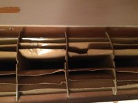
The lenses on the Beveridge are made of cardboard and also need some repair.
Do you have any tricks on how to rebuild the lenses?
Best regards, Frank
If not could you get enough SPL out of these?
I own 2 sets of the Beweridge loudspeakers and one set needs new stators. I also use Acoustat Monitor 4 with direct drive amps (rebuild by myself). These can play exceptional loud and have no problems in the bass region (subsonic).
The lenses on the Beveridge are made of cardboard and also need some repair.
Do you have any tricks on how to rebuild the lenses?
Best regards, Frank
Attachments
Hello Frank, In regards to my ESL top end, I drive them with a standard polarizing supply (similar to Jazzman's design) which produces approximately 2.5KV. Repairing a Beveridge lens is an interesting problem. In the process of building my speaker lens's I initially used very thin wood but in later experiments a thin smooth bendable cardboard. I have never needed to repair the cardboard lenses but I have fixed the wooden ones by edge gluing the broken ends together using temporary splinting to hold the 2 pieces together. Since cardboard has a wood fiber origin, it should glue together if you can reach the damaged site which will be the limiting factor. If you can post some photos of the damaged lens in question, I may be able to suggest some ideas how I would approach the problem. With best wishes,
Ted
Ted
Hello Frank, I took a careful look at your photo and it reminded me of the last time I saw a new model 5 at an audio show (1980"s). The lenses were warped even when brand new and the workmanship was sloppy. The speakers built by Beveridge before he sold the company were carefully made and the lenses did not warp because his material was different or maybe thicker. Using very thin cardboard causes the edges to warp no matter what you do to straighten them out. I found that out when I built experimental lenses out of 1/16"(1.6mm) thick cardboard. The only corrective solution which finally worked was to reinforce them with strips of thicker cardboard glued to the edges of the lens. This does change the terminal configuration of the lens (makes it thicker and with an abrupt transition) but I did not see any significant frequency aberations when measuring the result with pink noise and 1/3 octave realtime analysis. Nevertheless, this still led me to believe that cardboard may not be ideal for making lenses with the extreme curvature that the Beveridge design calls for. Some sort of flexible plastic may work better but I think the real solution is to design and build the lens in a 3D computer. However, before taking that expensive step, I would suggest you try gluing on some 1/4" strips of cardboard to the terminal part of the lens to see if that reinforces it enough. I used very small clamps to hold the pieces together while the glue dried but paper clips would possibly work. I put the reinforcing strips on the side with the widest opening. Good luck and best wishes,
Ted
Ted
You could also try taping and/or gluing straightened music wire to the edge of the cardboard. That would likely give you plenty of holding power without changing the lens geometry to a significant degree. Most hobby shops have 3 foot lengths of music wire in various diameters.
If you want to fabricate a plastic lens, thin polycarbonate is pretty friendly to work with: cuts, drills, taps relatively easily. Not easy to thermoform though.
ABS is much easier to form with heat, but isn't as tough overall.
A 3D printed lens would likely be quite expensive from a commercial printer. Thin, large structures have a tendency to warp when printed also, so I'd start with some smaller test prints before trying a full unit. Some stereolithograpy materials get brittle over time also, so careful material selection is required.
A bit of speculation about the original lens material: one benefit the cardboard likely had is better damping than plastics. They may have been using a limp cardboard to limit resonances in the lens structure. That could lead to a propensity to deform, but better overall sound.
Thanks for the feedback and ideas !
I also found that the shape does not effect the overall sound quality of the speakers but we all it like it to be more or less "perfect" (it eases our minds ha ha).
I could use some steam to reshape the cardboard and fix it as mentioned by you. I will try this at the upper ends of the speaker first.
What knd of stators did you use for you new ESL's? Is it wires or metal plate (like ML)?
I would like to use one set full range (no subs) as it was original this way. The other is slightly different (has a wider lens opening as it has subs).
The full range speakers are still working and have the metal frame stators as the other has plastic frames (these need to be replaced or refurbished) Full range is not required for this set.
Attachments
- Status
- This old topic is closed. If you want to reopen this topic, contact a moderator using the "Report Post" button.
- Home
- Loudspeakers
- Planars & Exotics
- Rebuilding Beveridge Circuit Board Stators