In the RAAL design the shaped magnets give a small wave guide of sorts and avoid the deep parallel sided slot and ( somewhat) the slot resonance that goes with it.
The claims that the shape gives a more uniform field I wonder about. The most uniform field in such a magnet arraignment comes from a deep parallel slot. The deeper it is , the more uniform the field
I recently got some quotes on shaped magnets. They are pressed / sintered into basic shape, then machined. Anyway to get a specific shape was much more expensive than standard available shapes. Use of iron poles to get desired shape is likely cheaper
BTW the Radiho design is actually quite an old design except for maybe the wiggy traces . A number of smaller versions of this were used by others in past. The Radiho is kinda a sized up version
I believe an old and loved Technics tweeter was quite similar. Used above about 5k I think and most of the speakers ive come across with it , the tweeter was melted from too many beers")
Also I have seen an even larger version in drawings. I think name on them was Nieuwendijk or something like that. They had a similar arraignment tweeter AND most interesting was one that was flat down to 100HZ!!! Absolutly massive magnet/pole structure. The driven section of a quite large diaphragm was about 3 by 4 inches. Undriven area of diaphragm was damped by close proximity to rigid structure.
The claims that the shape gives a more uniform field I wonder about. The most uniform field in such a magnet arraignment comes from a deep parallel slot. The deeper it is , the more uniform the field
I recently got some quotes on shaped magnets. They are pressed / sintered into basic shape, then machined. Anyway to get a specific shape was much more expensive than standard available shapes. Use of iron poles to get desired shape is likely cheaper
BTW the Radiho design is actually quite an old design except for maybe the wiggy traces . A number of smaller versions of this were used by others in past. The Radiho is kinda a sized up version
I believe an old and loved Technics tweeter was quite similar. Used above about 5k I think and most of the speakers ive come across with it , the tweeter was melted from too many beers
Also I have seen an even larger version in drawings. I think name on them was Nieuwendijk or something like that. They had a similar arraignment tweeter AND most interesting was one that was flat down to 100HZ!!! Absolutly massive magnet/pole structure. The driven section of a quite large diaphragm was about 3 by 4 inches. Undriven area of diaphragm was damped by close proximity to rigid structure.
Last edited:
In the RAAL design the shaped magnets give a small wave guide of sorts and avoid the deep parallel sided slot and ( somewhat) the slot resonance that goes with it.
The claims that the shape gives a more uniform field I wonder about. The most uniform field in such a magnet arraignment comes from a deep parallel slot. The deeper it is , the more uniform the field
I recently got some quotes on shaped magnets. They are pressed / sintered into basic shape, then machined. Anyway to get a specific shape was much more expensive than standard available shapes. Use of iron poles to get desired shape is likely cheaper
BTW the Radiho design is actually quite an old design except for maybe the wiggy traces . A number of smaller versions of this were used by others in past. The Radiho is kinda a sized up version
I believe an old and loved Technics tweeter was quite similar. Used above about 5k I think and most of the speakers ive come across with it , the tweeter was melted from too many beers
Also I have seen an even larger version in drawings. I think name on them was Nieuwendijk or something like that. They had a similar arraignment tweeter AND most interesting was one that was flat down to 100HZ!!! Absolutly massive magnet/pole structure. The driven section of a quite large diaphragm was about 3 by 4 inches. Undriven area of diaphragm was damped by close proximity to rigid structure.
3 or 4 inches should ber bit more i think
i made some smiliar with smaller magnets few weeks back, and where horizontal magnets. latest version looks actually more like the NEO drivers in push pull. aah well anyhow they are alll sort of the same.Attachments
Yea u would think it would be bigger however the actual diaphragm was more like 10 inches wide by 14 inches tall with just a small section in center was driven. All the undriven area was well damped and closed off by close structure flat and parallel to diphragm
I have built some like this and they are really good. All the problems of diaphragm resonances of a small diaphragm are gone BUT now you have a rather large overall driver. Very good however for large baffle dipole
I have built some like this and they are really good. All the problems of diaphragm resonances of a small diaphragm are gone BUT now you have a rather large overall driver. Very good however for large baffle dipole
If iron pole pieces become saturated you've reached the limit of the field you can generate so, unfortunately, they aren't really a direct substitute for shaped magnets in all situations.
I remember seeing the Nieuwendijk tweeter in an earlier edition of Martin Colloms' "High Performance Loudspeakers" book. I think it had a central magnet but I'm having a hard time tracking down the figure I can remember.
Very pretty diaphragms, WrineX! Are they chemically etched after a photo-process?
Few
If iron pole pieces become saturated you've reached the limit of the field you can generate so, unfortunately, they aren't really a direct substitute for shaped magnets in all situations.
this is true
I remember seeing the Nieuwendijk tweeter in an earlier edition of Martin Colloms' "High Performance Loudspeakers" book. I think it had a central magnet but I'm having a hard time tracking down the figure I can remember.
I think that is where I found it too. It didn't have a central magnet BUT it did have a central pole energized by the outboard magnets. I remember scaling up that picture to find that the magnet structure was huge and had to be to energize the iron poles. I made some planers based on the basic design of a diaphragm much larger than the driven section with undriven sections damped by close proximity stiff hard structure. It was easy to get quite smooth response down to 100hz or less this way.
Very pretty diaphragms, WrineX! Are they chemically etched after a photo-process?
Agreed! I too am curious how you made those
Few
If iron pole pieces become saturated you've reached the limit of the field you can generate so, unfortunately, they aren't really a direct substitute for shaped magnets in all situations.
I remember seeing the Nieuwendijk tweeter in an earlier edition of Martin Colloms' "High Performance Loudspeakers" book. I think it had a central magnet but I'm having a hard time tracking down the figure I can remember.
Very pretty diaphragms, WrineX! Are they chemically etched after a photo-process?
Few
I use the printer everyone should have if you do anything with this kind of stuff. a Xerox Solid ink printer. it prints wax, that functions as etch resist. only good for prototyping i think, since it sometimes it is a bit inconsistent . might be the age of my printer. but sometimes adhesion to alu is less then ideal and create pinpoint holes. overall i can make consistent foils but i have to match them, say 3 out of 4 an then maybe one sometimes even 2 i have to scrap. i bought it for flexible PCB used in the Rubanoide voice coil. it works better on the copper then alu.
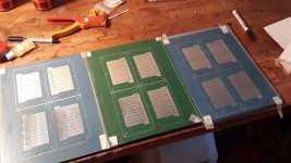
I just made these i had a weird idea of using wrinkling traces Really no idea where that came from
but i dont know if it even brings anything but , you need to try if you want to know in this case.You can see on the left there are some defects in the outer ring, not a problem, but adhesion to the alu remains hard, i try to clean it as good as possible. but stil. any one has an idea ? i used alcohol,thinner, and amonia. but it remains hit an miss. i also scuffed it a bit. but seems still complete random
with bigger coils i can path some defects with a sharpie, but with this small stuff and trace distance of 0.3 is tricky to patch up, usually ends in redoing it
Attachments
Last edited:
WrineX
I am really interested if you hear or measure any difference with the zig zag
is the "wax" an ink? or is there a special cartridge for that?
also what foil/backing/adhesive types and thickness are you using
In ultra high vacuum work they are super concerned about any contamination, especially oils. The cleaning is as follows..
1- Acetone
2- Isopropyl alcohol
3- deionized water
Alcohol doesn't dissolve oils all that well so Acetone is first with some scrubbing. Sometimes people use really HOT soapy water first ( good old Ivory soap with no fragrance best) but likely not an issue in this case
The alcohol removes the acetone
Di water isn't really necessary if rinsing with alcohol. Different labs have different procedures but I have found that the biggest contributors are the acetone fist followed by alcohol.
Last edited:
WrineX
I am really interested if you hear or measure any difference with the zig zag
is the "wax" an ink? or is there a special cartridge for that?
also what foil/backing/adhesive types and thickness are you using
In ultra high vacuum work they are super concerned about any contamination, especially oils. The cleaning is as follows..
1- Acetone
2- Isopropyl alcohol
3- deionized water
Alcohol doesn't dissolve oils all that well so Acetone is first with some scrubbing. Sometimes people use really HOT soapy water first ( good old Ivory soap with no fragrance best) but likely not an issue in this case
The alcohol removes the acetone
Di water isn't really necessary if rinsing with alcohol. Different labs have different procedures but I have found that the biggest contributors are the acetone fist followed by alcohol.
Thanks lowmass ill try that , i first thought about maybe pre etch ? with a light acid ?
The wax is the ink it self it comes in way overpriced blocks
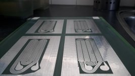
as usual well results in a push pull magnet system
I tried one panel heatgunned. and yes!! they stretch really nicely ! except where the arcs are to go down again , but there is not need to put heat there or make sure the arcs are on the frame and not on the foil.
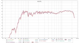
One thing to notice is the wiggled version has a DC impedance of 5.1 and the straight 6.8, while they measure as loud at same voltage. the straight one is a bit more efficient if same wattage was used.
Measured in room @ 1 meter no baffle
PIC 1 on freq response of both. dark red is wiggle red is straight
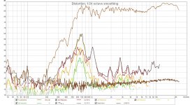
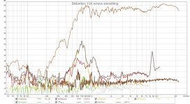
PIC 2 distortion measured a 2.83 volt @1 meter in room without a baffle Wiggle
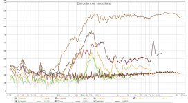
PIC 3 Straight has lower distortion then the wiggle. but its not major. the weird peak at 8.6K i need to find still. as seen in previous pic i left soem undriven alumnium there. might need to replace that with driven alu to make that undriven area as small as possible
Attachments
Last edited:
Thanks lowmass ill try that , i first thought about maybe pre etch ? with a light acid ?
Hmm yea that seems like a good idea. I would defiantly try that , but I would still get it oil free first. BTW finger prints have oil
The wax is the ink it self it comes in way overpriced blocks
Ha yep
PIC 3 Straight has lower distortion then the wiggle. but its not major. the weird peak at 8.6K i need to find still. as seen in previous pic i left soem undriven alumnium there. might need to replace that with driven alu to make that undriven area as small as possible
Hmm maybe that peak is where the zig zag magic is? Might have to do a few samples to be sure
Hmm maybe that peak is where the zig zag magic is? Might have to do a few samples to be sure
the insane peak is on the non zigzag. i am not to worried about it i can get rid of it. but it is also clear it is less in the zigzag. just overal distortion is slightly higher in the zigzag, and ouput although lower impedance is the same. hmm might be able to cramp in another zigzag winding..
maybe that solves some. i think the rest of the distortion is most likely top and botton and sides. so the actually NOT driiven area near the edge of the spacersyes I understood the peak is in the straight trace version, was saying maybe zig zag solves it?
I would expect zig zag to be just a bit less sensitivity because as you mention the alignment with magnet flux not as good as straight. That said , non symmetry is a way to smooth things out sometimes
BTW I find it best to do distortion measurements at a bit higher volumes. Around 95 db at 1 meter or even higher. Seems sometimes things are hidden at lower volumes
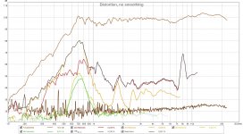
here is the same at 50 cm pic one
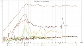
and at 50 cm with horn pic 2
weird output goes up and flattens with horn, but distortion rises as well. mainly second order 3th remains the same. maybe because i got a open back on the horn ?
and at 50 cm with horn pic 2
weird output goes up and flattens with horn, but distortion rises as well. mainly second order 3th remains the same. maybe because i got a open back on the horn ?
Attachments
Too bad the Xerox printers and supplies are too costly for me to justify. I can certainly see the usefulness. I’ll have to get creative with the Silhouette cutter I use to create conductors for planars.
i want the silouhete to
the thing is for soem stuff that thing is just better, and for some stuff (smaller ) my setup might be better. there is a dutch shop that resells those im really want to buy a version newer with higher dpi. they are used but prices are really awesome. mine starting from 150 yes allot on the clock but hell who cares. if i need to plut/cut something big i use my cnc with a drag knife i made or use just a permanent marker to plot it out and etch YouTube
yea I don't much listen at 95 db either BUT dynamics can certainly go past that.
How much it matters is a hot debate ha
At the same time doing a sweep at 95 db does not simulate that either
sweep is like as hard as it can get for any driverweird output goes up and flattens with horn, but distortion rises as well. mainly second order 3th remains the same. maybe because i got a open back on the horn ?[/QUOTE]
if you bring horn volume down to same level as no horn the distortion will be lower
also if you tame the resonance a bit with some felt or screen restriction on backside of driver you may see a big reduction in distortion
really nice response with horn ! have you done any off axis response curves with horn? I would like to see what directivity looks like
Last edited:
- Status
- This old topic is closed. If you want to reopen this topic, contact a moderator using the "Report Post" button.
- Home
- Loudspeakers
- Planars & Exotics
- piega factory tour video