oh in between so actually 2000 hz actually. thats rather close to the resonance. but they did use a steep filter so
The first time I viewed the Raidho videos I had the sound off so as not to disturb those around me. I enjoyed the videos quite a bit! I recently rewatched with the sound on and wish I hadn’t. Hit the mute button and you can focus on the parts that are interesting without the distracting nitwit!
If someone has seen a clear photo or diagram of the Raidho tweeter can they clarify the magnet locations and orientations? Are the N S N poles all facing the diaphragm? Is there a central bar magnet under the middle of the ribbon?
The measurements I’ve seen indicate that the tweeter has quite clean and smooth response with very few signs of resonances in the audible band. Simple design done very well. Probably a lesson I should be learning...
Few
The first time I viewed the Raidho videos I had the sound off so as not to disturb those around me. I enjoyed the videos quite a bit! I recently rewatched with the sound on and wish I hadn’t. Hit the mute button and you can focus on the parts that are interesting without the distracting nitwit!
If someone has seen a clear photo or diagram of the Raidho tweeter can they clarify the magnet locations and orientations? Are the N S N poles all facing the diaphragm? Is there a central bar magnet under the middle of the ribbon?
The measurements I’ve seen indicate that the tweeter has quite clean and smooth response with very few signs of resonances in the audible band. Simple design done very well. Probably a lesson I should be learning...
Few
oh i woul;d be interested in teh measurement. but yeah it is n s n or s n s 🙂 so there is a magnet in the middle and 2 on the sides. coil goes up in between the outer magnet and the middle one and then goes back down again between the other outer magnet and the middle to complete one turn, and it does that several times. still not sure if wiggling traces would be better , being able to stretch it with heat would eb a nice thing. but ont he other hand it might not be perfect if you look at the flemming rule. left hand rule that is. might need to make one. i did se this before somewhere can recollect where exactly. i think it is more fun to watch with sound 🙂 and maybe more interesting without 🙂 both are fun to be honest 🙂 haha.. but besides making fun of it is a clever and simple deisgn, that is done 1000000 times but why not and the speakers look very nice.
just a bit pricey for my taste. but as the dude mentions where are a luxury brand so everything needs to be perfect... well he kind of wraps it up
If it were audibly identical, but only 90%—or even 30%—of the luxurious fit’n finish, I wonder how much less they could charge. I guess the diamond-coated anodized aluminum drivers are likely to be expensive no matter what they do.
Few
Few
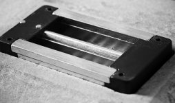
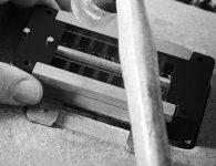
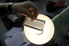
There are some high resolution black and white images of the tweeter construction posted on their website here: Downloads – Raidho
In case they are removed at some point, attached are 2 closeups of the magnet structure before the felt is put in, and then thumbnails of the other images. The central magnet is narrow, set lower and shaped. Note also that it appears one of the cavities is partially filled up; presumably to stagger cavity resonances.
Also, I had a pic showing the conductor trace layout of the previous non-ziggy-zaggy version.
Attachments

There are some high resolution black and white images of the tweeter construction posted on their website here: Downloads – Raidho
In case they are removed at some point, attached are 2 closeups of the magnet structure before the felt is put in, and then thumbnails of the other images. The central magnet is narrow, set lower and shaped. Note also that it appears one of the cavities is partially filled up; presumably to stagger cavity resonances.
Also, I had a pic showing the conductor trace layout of the previous non-ziggy-zaggy version.
nice Bolserst Hmm funny to see they dont use that big of a magnets, left and right magnet, have steel pole pieces by the looks of it but i cant see what is sitting on what. if you look at the finish it looks like bottom is magnet top is steel. butt hat makes me wonder about the formed center one. since it also looks rough like steel certainly not like nickel plating
but why actually raise the thickness of the whole thing. hmm
the big blocks are magnets. what the top pieces are i cant see 🙁 might as well non magnetic like alu or it is steel, or they are another magnet . although i think the rounded off you see is just steel rounded off. ?
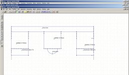
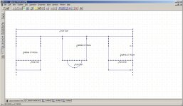
here a fast sketch of either using alu steel and another magnet..
i took the cruve 2mm above the metal/magnet/alu 1 mm would be more like it since it is only the double sides tape in between.
yes i did it upside down because i could not get the arc to mirror.. so i mirrored the rest 🙂 haha
here a fast sketch of either using alu steel and another magnet..
i took the cruve 2mm above the metal/magnet/alu 1 mm would be more like it since it is only the double sides tape in between.
yes i did it upside down because i could not get the arc to mirror.. so i mirrored the rest 🙂 haha
Attachments
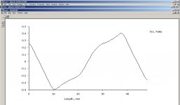


oh found some measurements. pretty nice they even have them most high end dont publish anything
http://raidho.dk/wp-content/uploads//Raidho-Acoustics-Ribbon-Tweeter-FTT75.pdf
pretty damn smooth. not sure if it it measured at 1 watt or 2.83 volt but looks like eff is 86- to 93dB. . pretty impressed by how smooth it is. nice !
http://raidho.dk/wp-content/uploads//Raidho-Acoustics-Ribbon-Tweeter-FTT75.pdf
pretty damn smooth. not sure if it it measured at 1 watt or 2.83 volt but looks like eff is 86- to 93dB. . pretty impressed by how smooth it is. nice !
Bolserst to the rescue, yet again! Great photos! Thanks very much. They make it clear there's a central magnet (or at least pole piece--I'm guessing magnet).
They also make it clear that the outer two magnets lie in a different plane than the central one, and by quite a bit. I had a sense that might be true, which is why I was asking if the outer magnets have their poles facing the diaphragm (as is typical of planars) or facing each other (as is typical of simple ribbons, although the two outer poles would be the same polarity in this case).
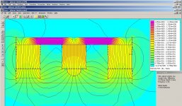
WrineX's very helpful simulations look like they're based on the poles facing the diaphragm. That's certainly the usual configuration, but given the height difference between the central magnet and the two outer magnets, it seems to me that the outer magnets might have their poles facing inward, toward the middle of the tweeter. I hasten to add I have not yet done any simulations so this is purely a seat-of-the-pants guess at what the field lines might do. It "feels" to me like the diaphragm might end up immersed in nicely oriented field lines if the central pole were aimed at the diaphragm and the outer poles were aimed inward. I stand ready (and expecting) to be corrected if someone beats me to the simulations!
Few
They also make it clear that the outer two magnets lie in a different plane than the central one, and by quite a bit. I had a sense that might be true, which is why I was asking if the outer magnets have their poles facing the diaphragm (as is typical of planars) or facing each other (as is typical of simple ribbons, although the two outer poles would be the same polarity in this case).
WrineX's very helpful simulations look like they're based on the poles facing the diaphragm. That's certainly the usual configuration, but given the height difference between the central magnet and the two outer magnets, it seems to me that the outer magnets might have their poles facing inward, toward the middle of the tweeter. I hasten to add I have not yet done any simulations so this is purely a seat-of-the-pants guess at what the field lines might do. It "feels" to me like the diaphragm might end up immersed in nicely oriented field lines if the central pole were aimed at the diaphragm and the outer poles were aimed inward. I stand ready (and expecting) to be corrected if someone beats me to the simulations!
Few
Bolserst to the rescue, yet again! Great photos! Thanks very much. They make it clear there's a central magnet (or at least pole piece--I'm guessing magnet).
They also make it clear that the outer two magnets lie in a different plane than the central one, and by quite a bit. I had a sense that might be true, which is why I was asking if the outer magnets have their poles facing the diaphragm (as is typical of planars) or facing each other (as is typical of simple ribbons, although the two outer poles would be the same polarity in this case).
WrineX's very helpful simulations look like they're based on the poles facing the diaphragm. That's certainly the usual configuration, but given the height difference between the central magnet and the two outer magnets, it seems to me that the outer magnets might have their poles facing inward, toward the middle of the tweeter. I hasten to add I have not yet done any simulations so this is purely a seat-of-the-pants guess at what the field lines might do. It "feels" to me like the diaphragm might end up immersed in nicely oriented field lines if the central pole were aimed at the diaphragm and the outer poles were aimed inward. I stand ready (and expecting) to be corrected if someone beats me to the simulations!
Few
Hi few would the coil just not twist if they where like ribbon driver ?
Yes, the diaphragm would certainly twist if my notion about nicely behaved field lines is wrong. Clearly a FEMM simulation will be easiest way to determine what the field looks like.
Few
Few
Well at least you can see they use the same magnet in all 3 and use different metal on top by the looks of it . 2 x square 1x rounded. At the pic eith the rounded one you can see the rounded piece is slightly smaller then the magnet itself. But how i do my best simulating. The sides left right keep being stronger then the field in the middle. But then again it moves more in the middle so overal it might uniformly ? At the same time it is less linear in that area. Also the coil at the edges would be rather hard driven so close to the magnet although the foil wont let it move that much. Would love to have a measurement of them 🙂 i also looked for patents but found none. About the wigly bit 🙂
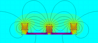
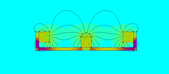
I made a quick attempt to compare the two different outer magnet orientations. The dimensions aren't realistic, I was just looking for a quick sense of how the symmetry affects things. The first figure shows the conventional planar magnetic set-up. The second shows the outer magnets with their poles facing inward.
Few
Few
Attachments
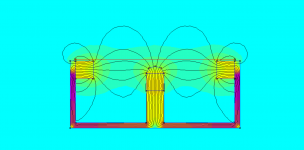
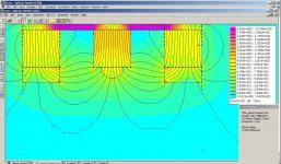
For the "poles inward" orientation the steel in my first version was short circuiting things. Here's a modification that improves things a bit. Clearly not the holy grail even with the improvement.
Few
Yeah the steel does not work in that regard. Maybe a non magnetic material. Ill take alook when im home but i can imagine not being the bomb 🙂
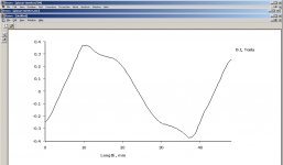
hmm what i noticed in my sims and also in yours (even more with the magnets to the inside) is that the best field lies actually below where the foil would be 🙂so with excursion it would not be very even i believe
What I see..
Yes N-S-N basic configuration BUT with iron poles on ALL magnets.
Outside magnet poles a bit higher than center pole so diaphragm can move without hitting center pole, and diaphragm attached right on surface of outer poles
Looks to me that center magnet is not shaped mag BUT the iron pole on it is smaller than outside poles. Similar result to a shaped magnet BUT much less expensive to make.
It is a basic planer layout HOWEVER what we are seeing is a great deal of refinement of that basic design. I see refinement in every single area all adding up to a great end result. Well done
Yeah I fiddled a bit with the height of the central magnet to get the best looking result. I guess you could mount the diaphragm at the midpoints of the side magnets, where the field lines are ideally oriented. It would end up being just a modified version of a traditional ribbon in that case. RAAL claims to have developed some fancy magnet shapes that yield a uniform field for their ribbon but I haven't seen any details on what they are doing (or what he is doing if it's really mostly Aleksander). Apparently RAAL machines the NdFeB into a complicated shape before magnetizing it. A bit out of the DIY realm...
Few
Few
My simple model used shaped steel on the center magnet but no pole pieces on the outer ones. The outer magnets or poles look like they have simple rectangular cross-sections, in any case. Now that I've played with some modeling I'll have to take another look at the photos and see if I can pick out any more details.
Few
Few
- Status
- Not open for further replies.
- Home
- Loudspeakers
- Planars & Exotics
- piega factory tour video