It's rather simple to estimate UL =L*dI/dt. So if bandwidth is limited and no resonances are present you are OK. It well might be to have series resistor to tame Q factor of LC tank you're getting. You are cutting idle power two times for single-ended design. I can't provide reference as of now but there is a guy who made single ended inductor loaded direct tube amp.Hi,
regarding R- versus L-loading see attached pic.
It prooves that the anode voltage with an inductie anode load can easily swing beyond the supply voltage.
Both MOSFETs are set to the same idle current bias points and receive the same input signal.
"Direct drive amps and ESLs are pretty efficient compared to..."
Well they become pretty inefficient towards the upper audio bandwidth too.
If You design for full power bandwidth at 20kHz You end up with several hundreds of W to a kW of mostly wasted power.
jauu
Calvin
Again, I don't have the education to dispute Calvin's model, but it sounds like "the bumble bee can not fly" flawed theory.The formula reads Ip = (Cload + Cx) x pi x f x Vpp with Ip: peak load current, Cload: capacitance of the connected ESL, Cx: other capacitaces from cabling etc, pi: 3.14, f: frequency of the driven signal Vpp: peak-to-peak signal voltage
Folks have been making loud treble for a long time with modest Quad amps. Likewise, while my DD amp was sold before REW became my regular buddy, I sure got lots of nice cymbal crashes and I plotted freq responses and distortion that seemed pretty good as far as my tools allowed.
What's the flaw?
B.
Hi,
as I wrote .... a full power bandwidth of 5kHz is sufficient for most music material, as there's little high level high frequency content in music.
Also, with growing age human bandwidth comes down and from 5kHz on one might not be able to hear even the first harmonics anymore.
Even if current clipping occurs -with the associated fall of the output voltage- it might not be audible
jauu
Calvin
I fully agree with Calvin. When analysing spectral energy contents of music, you see regular peaks of full amplitude up to 4-5 kHz. Above that the energy content quickly drops off. So a DD amp that is able to provide full voltage swing up to 4kHz will do ok. But that is quite a challenge as ESL's are very hungry for current in the mid frequency range.
I built several DD amps in the past and one of the first prototypes I built ran from 1kV rails, producing about 1.7kVtt between the stators. It was a ccs loaded SE design so the maximum output current more or less equaled bias current. Even at 25mA bias (dissipation limit) it was still constantly current clipping under music, which surprised me a lot. So I did some elaborate measurements on current demands of segmented wire stator ESL's. My conclusion was you'll need a minimum of 25 mA per kV voltage swing for a decent DD amp, preferably more. It is also very important to obtain sufficient open loop bandwidth and slewing in the power stage so it can actually deliver that current distortion free, which is not that easy.
If you want to build an amp that can compete with the output of a good transformer, you'll need at least 7kV swing so let's say 4kV rail voltages, and >200mA peak current capability. That is > 1.6kW dissipation for a CCS loaded SE amp. Per channel. No, DD is not very practical at all...
Bumble bee still can't fly.
But I should mention that my brutish amp driving 1:100 transformers (very very low impedance at high frequencies) sometimes trips the emergency button when doing loud high freq tests (maybe 400 watts in the region we are talking about here... hard to say how the situation looks to the protection circuits).
Hard to precisely assess when people post past experience - as valuable as that always is - because bias, size of panels, gap, etc. aren't posted.
How come we aren't roasting those little step-up transformers if we're putting 1.6kw of power through them for testing over 4kHz?
Nobody argues about the statistics of music power. The question is what kind of DD amp results in loud music in ordinary home rooms.
Whatever the theoretical problems with DD, like with motional feedback, most everybody who has tried it loves it.
Ben
Hi,
the wattage that can be transformed rises with rising signal frequency.
Big is only required for low frequencies.
Ever wondered about the size of the transformers in a SMPS?
Keep in mind also, that a transformer only deals with signal power where the power peaks are typically short.
A amplifier though 'wastes' idle power all the time which -depending on the bias setting and the efficiency of the circuit topology- can be vastly higher than the signal power.
Almost all ESL amps were of SE type whith a maximum efficiency of 50% ... not taking into account the efficiency of its power supply and the fact that four output stages are required for stereo.
So far I haven't seen a pushpull DD-amp biased in class-B.
jauu
Calvin
Last edited:
Do you include dust removing effort as well as sun tracking mechanotronics? What about real life inverter and batteries. How much is for the ones with 10 years life span without repair. Still it's more than reasonable where central grid is absent - no need for fuel delivery/storage to begin with.
Cheers, Alex.
I think we have plenty of rain here not to have too much trouble with dust, and most solar panels are placed on rooftops without any mechatronics. I don't know precisely what René van Swaaij did and did not include in his estimate, but I guess the most energy-consuming part of the production process is the purification of the silicon by zone melting or similar techniques. Considering the relatively small silicon area used in the inverters as compared to the panels themselves, that would mean that including the inverters would not increase the energy pay-back time much.
By the way, energy storage will indeed become an issue. There are some creative ideas about it, but most are not worked out sufficiently for large-scale use yet.
Getting back on topic again:
A 20 kHz power bandwidth is indeed not necessary for most types of music, otherwise FM radio could not work. With 50 us pre-emphasis in Europe and 75 us in the US, it has power bandwidths of 3183 Hz and 2122 Hz, respectively.
Besides, any well-designed flat-panel full-range ESL has segmented stators, because otherwise it beams like crazy at high frequencies. When the sections are made small enough both horizontally and vertically to ensure that the listeners are in the far field, the vector sum of the currents through all sections has to be made frequency-independent to get a flat response. When the current through a capacitor is frequency-independent, the voltage across it has to drop with 20 dB/decade. This also reduces driving requirements. It is explained much clearer than I could ever explain it on Frank Verwaal's website.
Sorry for off-topic. Equipment designed to last 10 years and has 10 years warranty is insane price wise. That was the point.
Moreover, you do not need electricity a home during day time - most people work when sun shines. That said total is around 20 grand with 30% gov't credit and 5 grand subsidy @ US. typical inverter costs 4 grand and need to be replaced every 5 years max. "The average U.S. household can break even on their solar energy system in just 7.5 years" Source: Solar Electric Power Association, 2015 Market Snapshot
Again, it assumes that you consume energy during day time which is not true.
Look at European natural gas saga and decide for yourself.
However tide hydro stations and wind turbines do allow Norwegians to have free electricity.
Back to the topic:
I do work with SiC mosfets and 1200V ones are already quite robust and have rather small parasitics. 1700 V ones exist as well and they will be followed by 3500 V in near future. So one may just purchased some and create lethal toy. That said 1500 V rms from a transformer is not better by any means from a safety stand point.
Last edited:
Hi there!! ")
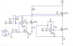
I have been really busy lately, but in the meantime I would like to share my latest DD design I did some time earlier this year in Circuit maker.
Of course like everything else I haven't the time to test it yet.
I do like this design as it features a voltage settable bias current, it is only for a 1kv supply but a pair of them this will provide up to 2kv p-p.
Once I test this I will work on stacking the FET's for a higher supply voltage and swing.
So, I post this here should anyone want to give it a go.
The sim's work Great!!
This version is just a single amp itself without a phase splitter.
The output is taking from the middle of the two FET's.
This is a working simulation rough draft so I don't have any sim data available at this time around.
I will post the CKT file and sim data if I can find it, else I will have to re draw it to produce them.
No biggy really, just extremely busy working on other stuff that must be done First.
It does not require any floating supplies like the Neil S. Mckean ESL amplifier found at TAC or high power resistors the top FET takes care of that..
Cheers !!

jer
I have been really busy lately, but in the meantime I would like to share my latest DD design I did some time earlier this year in Circuit maker.
Of course like everything else I haven't the time to test it yet.
I do like this design as it features a voltage settable bias current, it is only for a 1kv supply but a pair of them this will provide up to 2kv p-p.
Once I test this I will work on stacking the FET's for a higher supply voltage and swing.
So, I post this here should anyone want to give it a go.
The sim's work Great!!
This version is just a single amp itself without a phase splitter.
The output is taking from the middle of the two FET's.
This is a working simulation rough draft so I don't have any sim data available at this time around.
I will post the CKT file and sim data if I can find it, else I will have to re draw it to produce them.
No biggy really, just extremely busy working on other stuff that must be done First.
It does not require any floating supplies like the Neil S. Mckean ESL amplifier found at TAC or high power resistors the top FET takes care of that..
Cheers !!
jer
Attachments
Last edited:
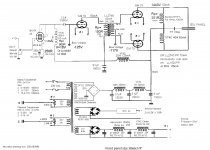
Thanks, Gerald.I am glad to see some pic's of your ole' DDAmp !!
Here's some annotation to give prospective builders some perspective on the pieces needed, apropos post #46.
The amp weighs a lot. I brazed two steel chassis together to form a big one.
The 5 silver boxes in the back are HV oil-fills caps.
The B+ comes from two transformers, I think. There also are transformers for bias voltage, filaments, and transistor power. Hidden inside is a transformer for adjusting the speed/noise of the cooling fan which blows out of the little crack at the top front of the cabinet bottom box.
You can see the red test-lead HV wire. Spark plug wire works too. (For a tweeter with about 1200v bias, I used rather ordinary 15A flexible extension cord to the panels; so long as there's lots of rubber around the wires good for several meters.)
In the foreground, there is a large red resistor grounded at one end that is used for draining HV from any speaker-panel plugs removed from the chassis. Don't build without one.
At least in pre-web days, it was helpful to live in a big city with surplus electronics stores.
Ran this great amp for decades but it has been maybe 15 years since it moved on to other hands. Glad to answer any questions I can.
I remain convinced I never made more perfect ESL sound, luscious and transparent, than with DD.
B.
Last edited:

DD ESL amp
Here is a direct drive amp I designed. It works perfectly but sounds much more PP than Single Ended. I use it to drive two 3'x2' panels per channel spaced at 1/8" giving 1nF capacitance per channel.
It does not work as a direct drive as the bass volume is too low. I use an active third order crossing over at 200Hz.
It outputs 1040Vrms with a 1kHz sine wave before distortion sets in and the sine wave breaks up.
Playing the Eagles Hotel California and measuring the true rms value of the voltage and current and knowing the capacitance of the panel I was able to calculate an average frequency of 1.8kHZ. Obviously the higher the frequency of the music the more current is drawn
Attachments
It outputs 1040Vrms with a 1kHz sine wave before distortion sets in and the sine wave breaks up.
How is the sound level with this supply voltage? Does it play loud enough for you?
Jan
Here's an interesting thread I'm waiting on to continue
Build me a ss direct drive ESL amp, please
Build me a ss direct drive ESL amp, please
Sure, but aren't you curious how they would compare? I have Acoustat Monitor 3 with DD OTLs and I also have Model 3 with interfaces coupled to either ss or tube. There is no comparison. The DD OTLs are far superior. I want to hear how DD ss compares to DD OTL. It seems this scenario is the final arbiter in regards to ss vs. tubes. It's the interface that's getting in the way.Why solid state? Tubes and direct drive ESL is a perfect match.
My Beveridge is playing just awsome and you can see the schematics above nr:73
The tubes are dirt cheep and there is a lot of them... so what are you waiting for guys and girls?
Why solid state? Tubes and direct drive ESL is a perfect match.
My Beveridge is playing just awsome and you can see the schematics above nr:73
The tubes are dirt cheep and there is a lot of them... so what are you waiting for guys and girls?
Hear, hear! They are definitely a good match for the output stage, like in your circuit. Beam tetrodes meant for TV line stages biased at a relatively low G2 voltage work fine there. Attached are the schematics of my variant, which was dreadfully inefficient and couldn't play loud enough, but sounded great. In retrospect I think I also should have used an SRPP-like output stage (far more efficient than what I used), and maybe a few transformer secondaries in series instead of the cascade for the high-voltage supply (would allow a much higher supply voltage - with a cascade the output resistance increases rapidly with the number of stages).
Attachments
Why solid state? Tubes and direct drive ESL is a perfect match.
My Beveridge is playing just awsome and you can see the schematics above nr:73
The tubes are dirt cheep and there is a lot of them... so what are you waiting for guys and girls?
Does the Modjeski direct drive amp use that circuit too?

[FONT=arial, helvetica]Output 4000 volts at 1/3 amps front to back electrode to electrode[/FONT]
- Home
- Loudspeakers
- Planars & Exotics
- Any Direct Drive ESL Amp projects someone could share?