Hmmmm…my posts must not have come across as I intended, sorry about that.…I'm just a messenger who transformed the simple equations into a simple Delphi program, don't shoot me. One thing is good with the program though, it made it easy to spot faults in the equations! (if there are any). If anyone has better ribbon simulation equations, let me know so that we can improve the program together.
I was not trying to shoot the messenger, the "thumbs up" emoticon in the post was intended to praise the messenger. In any case, I was trying to point out the short comings of the equations (which your program makes it very easy to identify) and suggest better ones based on the proven Walker equation for ESLs. If interested, I can also provide details for incorporating an estimate of high-frequency roll-off due to mass into the equation without getting overly complicated.
I agree this would be very useful.Ribbon temperature would be a nice thing to know at different current flows...
Power dissipated in the ribbon is easy to calculate…would need to look into heat transfer equations for a vertical flat plate.
I hadn’t mentioned it but a few days after testing the 0.65µm ribbon in post #122 I was listening to some music on it.
I turned up the volume too high and the ribbon vaporized into a whiff of smoke.

As luck would have it, I recently acquired this book. The equations you are using did not come from it. The equations you are using actually seem to me to be better than the simple ones derived in Chapter 2. That was one of the reasons I was interested in learning how they were derived. The book has some more complicated models developed later in Chapter 5 that include radiation impedance and size of gaps between ribbon and magnets. These models show trends for mass affecting mainly the top octaves, which match measurements. But, the models were developed for infinite baffle ribbons so the radiation impedance portion would need to be changed for dipole modeling. I was in the process of modifying the model for dipole ribbons when the idea of using the simple Walker Equation came to me.I've been googling "Simple ribbon equations" and found that the origin probably is in "Justus V.Verhagen: Ribbon Loudspeakers, side 8.
Very nice, thanks! I assume these measurements were all with nearly identical current thru each ribbon?Here's a width comparison for a 40cm long ribbon, 15mm gap. Ribbon width 10mm (red), 11mm (green), 12mm (orange), 13mm (blue), 14mm (black):
These trends clearly show that you want to minimize the airgap between the ribbon and magnets to avoid SPL loss at lower frequencies. It also shows that at higher frequencies where the airgap is not a player that the SPL is unaffected by ribbon width. If you reduced the gap between magnets for the 10mm ribbon to 11mm, the low frequency loss would be gained back. In addition, with increased field strength, the overall SPL level should increase.
Aaaah…so excursion was your limiting factor.For the recent designs I choose a 20mm gap to keep the excursion small because the field is not linear. I simulated a lot of designs in FEMM and found a 20mm gap to be the best compromise between field uniformity and radiating surface.
How much excursion were you estimating for your 20mm design?
I guess it depends on target maximum SPL and how low in frequency you planned to cross over.
Last edited:
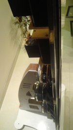
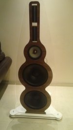
A picture of the brass test frame:
View attachment 526097
Two magnets in stead of three. The idea is to make the ribbon 12cm long so as to move the mounting point out of the gap and provide some flexibility.
regards,
Gerrit
Did yo play the brass version? How did you mount the membrane on these? Outcome - findings?
//
Did yo play the brass version? How did you mount the membrane on these? Outcome - findings?
//
Sorry, no progress as of yet. I've other things on my mind right now.
regards,
Gerrit
Attached plot shows my build-up for modeling the Neo-8.
Actually, now that I look at it, since the green line rolls off a bit more than the purple starting at 1kHz, I was probably included the mass of the slugs of air in the holes thru the steel plates as well.
If interested, I posted some diffraction comparisons for a "new-to-me" BTM diffraction modeling technique that diyAudio member jlo pointed out to me. Even considering only 3rd order diffraction components the matching with measured data is extraordinarily good, much better than the DED/EDGE models.
http://www.diyaudio.com/forums/mult...ffraction-dipole-radiation-9.html#post4249318
Hi Bolserst,
Your modeling of the Neo8 has piqued my interest. I've been playing with very simple models of ribbons and magnetic planars lately. It looks like you've had a lot of success modeling the resonance of the holes in the magnet/perforated steel structure holding the Neo8 together. I'm wondering why the Neo3's don't display a similar resonance. I measured the size of the holes on the Neo3's and Neo8's I have and was surprised to find that the holes are slightly larger and deeper on the Neo3's even though they are a tweeter.
Dan
p.s. sorry for sending this O.T. but I didn't think this questioned deserved it's own topic, at least not yet.
Last edited:
Just to be clear, the ~13kHz peak in the Neo8 response results (to a first approximation) from the mass of the (diaphragm + conductors) resonating with the compliance of the air trapped between the diaphragm and the perforated steel plates. The holes in the steel plates do add a lumped mass on the other side of the air space compliance, but their effect is small in the case of the Neo8 (and Neo3) because the diaphragm mass dominates. See post #196 for more details. BTW, the Q and magnitude of the peak is partly determined by the % open area of the plates.… It looks like you've had a lot of success modeling the resonance of the holes in the magnet/perforated steel structure holding the Neo8 together.
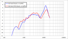
My recollection of measuring a borrowed Neo3 was that it had almost exactly the same peak in the response as the Neo8, just slightly higher ~14kHz. Since it didn’t provide a substantial improvement in HF extension compared to the Neo8, I never acquired any of them. So, unfortunately, I don’t have any of my own measurements, but you can see some measurements of a Neo3PDR in dipole mode here:I'm wondering why the Neo3's don't display a similar resonance.
http://www.diyaudio.com/forums/mult...le-dipole-beyma-tpl-150-a-38.html#post1990640
The PDR version has some additional acoustic damping from a thicker layer of felt between the diaphragm and steel plates on the outer third of the diaphragm.
Find attached on overlay of the 1/3 octave smoothed on-axis measurement from the link above, and my measurement of a Neo8.
Note that since the width and length of the Neo3 are nearly the same, the dipole notch and boost are a little more pronounced than for the Neo8. Other than that, the responses are remarkably similar.
Attachments
Thanks for the reply Bolserst. Your model is most helpful. I don't have Beranek, but I think I can derive most of the required values. I hadn't seen the data you plotted before, it makes sense that the Neo3 should have a similar peak to the Neo8. I had seen Zaph's measurements and BG's published measurements which seemed close to each other and neither showed such a peak for the Neo3. Both did show a smaller peak above 20 kHz on axis. After measuring some dimensions on my Neo3 I calculate the peak should be around 13-14 kHz as your plot shows (I used a simple air spring calculation).
Zaph's measurements were with the rear cup in place, I'm guessing it was the small one. I wouldn't have thought it would have an effect on a peak at higher frequency though. I haven't measured mine yet, but now I'm curious to see if it exhibits expected behavior you showed. Mine have rear cups, but much deeper than I had seen in pics on the web. They're about 2.5" deep and have almost a teardrop shape.
Anyway, sorry to push this off topic again but thanks for your help Bolserst.
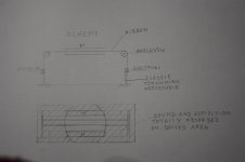
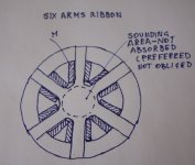
Corrugation increase weight of the ribbon per linear inch ( two sides of a triangle instead of one)
The direction of emission is perpendicular to the faces of the ribbon so emission is subject to interference.
What do you think about this scheme in which corrugated parts are out of magnet so they work only like a suspension and wich sound will be absorbed?
The direction of emission is perpendicular to the faces of the ribbon so emission is subject to interference.
What do you think about this scheme in which corrugated parts are out of magnet so they work only like a suspension and wich sound will be absorbed?
Attachments
Corrugation increase weight of the ribbon per linear inch ( two sides of a triangle instead of one)
The direction of emission is perpendicular to the faces of the ribbon so emission is subject to interference.
What do you think about this scheme in which corrugated parts are out of magnet so they work only like a suspension and wich sound will be absorbed?
The corrugation is necessary to provide lateral stiffness. I tried a flat ribbon with 1cm corrugation at each end (though still in the gap) this didn't work, there was too much distortion.
I specifically tried to avoid sharp triangles, the method with the ribbon flat cable results in a more sine wave like profile.
regards,
Gerrit
The corrugation is necessary to provide lateral stiffness.
I agree but the magnetic field shoud be very different going from the two poles
and the longitudinal tension of ribbon too weak
(though still in the gap)
out of gap is an essential condition for the scheme
results in a more sine wave like profile.
I do not agree, the scheme is just to avoid the sinusal deformation of the ribbon that works, in the known scheme, just like a string of a guitar ;
ideally if corrugated suspension has no longitudinal stiffness the ribbon moves like a piston; this can be obtained by a scheme that I do not want show now but you can imagine like a suspension of a wheel of a car.
Last edited:
Talking about corrugation : https://3.bp.blogspot.com/-EzL9XVqj...tej_isak_test_2016_new_2017+-+1+%281%29-1.jpg
The bass driver seems to be a Eminence Delta (Xmax = 2.7mm)
The bass driver seems to be a Eminence Delta (Xmax = 2.7mm)
What do you think about a stripe ribbon obtained making many cuts on it?
( the two terminal ends can be not cut according to the scheme in picture)
By this way every stripe moves according to the magnetic field without forcing the ribbon part at its sides that are moved by different forces
Those different forces are the ones that make necessary to corrugate the ribbon or to tension it
A laser cut, after the ribbon has been mounted on the frame, would not stress the ribbon; more are the cuts and more each strip is free to move according to its force.
Attachments
What do you think about a stripe ribbon obtained making many cuts on it?
( the two terminal ends can be not cut according to the scheme in picture)
By this way every stripe moves according to the magnetic field without forcing the ribbon part at its sides that are moved by different forces
Those different forces are the ones that make necessary to corrugate the ribbon or to tension it
A laser cut, after the ribbon has been mounted on the frame, would not stress the ribbon; more are the cuts and more each strip is free to move according to its force.
I don't see how this would improve performance as you introduce several degrees of freedom for the ribbon to move, but of course you could try. I certainly won't because it will make replacing the ribbon very complicated and expensive. Because the ribbon is so fragile it should be easy to replace it.
regards,
Gerrit
Just to show you my last project with unfinished 30cm long ribbon. Ribbon is still under production. Instead temporary mounted 2 Raven's.
Attachments
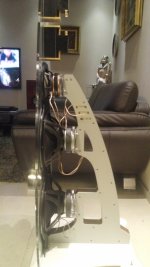
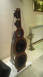
Just to show you my last project with unfinished 30cm long ribbon. Ribbon is still under production. Instead temporary mounted 2 Raven's.
What's the reason for making the ribbon 30cm long? what is the intended crossover?
regards,
Gerrit
I don't see how this would improve performance as you introduce several degrees of freedom for the ribbon to move, but of course you could try. I certainly won't because it will make replacing the ribbon very complicated and expensive. Because the ribbon is so fragile it should be easy to replace it.
regards,
Gerrit
Gerrit,
I see you have the key of the door.
It seem me you make happen what you want:
Good - no good
Right - not right
Helpful - not helpful
Without readind or understandig, it seems like if world must stop.
No more interest to go on, I think the door will not be opened.
Good by to every one - ciao!
p.s.
the attached is one of the schemes for solving the problems of a excited ribbon: tensioning, reducing ribbon weight ( corrugating increases weight very much ),dampening ribbon structural modes, control of emitted sound.
Attachments
Cheer up, Middle, I've tried your scheme with splitting the membrane, and it did not lower the distortion.
In fact, the sound was pretty bad. A better way is to increase the membrane thickness in the middle third of the width of the membrane, increasing the flow of current where it's needed.
But the best sounding membrane I've produced is an ordinary 5 uM one with Gerrits cable corrugator.
A peculiar fact I've found in my experiments, is that a 10 uM membrane sounds almost as good as a 5 uM membrane if you're using a Metglas transformer, and that 5 uM membrane have a tendency to get tiresome in the highest octave when Metglas driven!
The only ANELASTIC theatment of ribbon movement at is ends and near its ends would require a lot of experimentation.
Rigid piston means move toghether all the surface or extinguish the faster possible the movement of the ribbon structure.
Less weigth for ribbon, more weigth for dampening ribbon structural modes .
Someone tryed by mylar or so but I think there is a lot to do, starting from the funcional separation of the surface that give sound from the one that supports that.
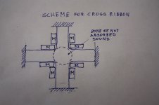
What do you think about a scheme of cross ribbon?
Rigid piston means move toghether all the surface or extinguish the faster possible the movement of the ribbon structure.
Less weigth for ribbon, more weigth for dampening ribbon structural modes .
Someone tryed by mylar or so but I think there is a lot to do, starting from the funcional separation of the surface that give sound from the one that supports that.
What do you think about a scheme of cross ribbon?
Attachments
- Home
- Loudspeakers
- Planars & Exotics
- DIY ribbon dipole tweeter, reductio ad minimum