But not entirely flat.... "standing wave suppressing pattern..."
http://www.6moons.com/industryfeatures/roadtourserbia/raal4_2.jpg
//
http://www.6moons.com/industryfeatures/roadtourserbia/raal4_2.jpg
//
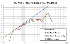
Attached plot shows my build-up for modeling the Neo-8.…will see if I can locate a comparison plot.
This was a screen grab from work in progress, so the legend is a bit cryptic as can be expected.
I will try to describe below…
Red Curve: Measured Data
Blue Curve : the +6dB/oct slope of ideal massless, baffleless radiator measured in far field
This is the usual starting point for modeling ESLs and ribbons that are small relative to measuring distance.
Purple Curve: Response if diaphragm mass is considered
Green Curve: Response if diaphragm mass + acoustic properties of cavity between diaphragm and plates is considered
Actually, now that I look at it, since the green line rolls off a bit more than the purple starting at 1kHz, I was probably included the mass of the slugs of air in the holes thru the steel plates as well.
One other thing to note is the notch in the measured data at 6-7kHz( and slight hump an octave lower) which is due to diffraction from the baffle formed by the steel plates surrounding the hole pattern thru with the sound is emitted. I have been working on modeling for that as well, but is a tough nut to crack as radiation impedance changes as baffle dimensions changes. With “heavy” dynamic drivers this isn’t an issue for modeling and can be ignore, but with ribbons and ESLs it has a pronounced effect on the response.
If interested, I posted some diffraction comparisons for a "new-to-me" BTM diffraction modeling technique that diyAudio member jlo pointed out to me. Even considering only 3rd order diffraction components the matching with measured data is extraordinarily good, much better than the DED/EDGE models.
http://www.diyaudio.com/forums/mult...ffraction-dipole-radiation-9.html#post4249318
Attachments
Wow, those simulations are almost spooky in their ability to capture the details of real-world performance! That certainly justifies confidence that the key effects are being taken into account. Very cool!
Optimization:
a) 3x5cm, or
b) 1x15cm
magnets?
//
Of course 1 x 15cm would be preferable but the force could be a serious problem. The magnets are brittle and it could prove to be very difficult to handle them. Two of those magnets are also potential finger guillotines. These were my reasons for choosing 3 x 5cm.
regards,
Gerrit
I've been experimenting with 2µm mylar foil, here are some results:

As you can see there hardly any improvement with respect to earlier results. The ribbon does get sturdier with the mylar backing but that's about all. The simple shellac coating seems to be the most effective so far:

It's time to mount the drivers on he loudspeakers and give them a listen.
regards,
Gerrit
As you can see there hardly any improvement with respect to earlier results. The ribbon does get sturdier with the mylar backing but that's about all. The simple shellac coating seems to be the most effective so far:
It's time to mount the drivers on he loudspeakers and give them a listen.
regards,
Gerrit
Looking super. How do you dispose 5u shellack?
//
Thanks🙂
I don't know how thick the layer is. The aluminium foil is 4.6µm (etched from10µm). Shellac is a solution in alcohol so it has low viscosity. I applied it with a cotton swab, one stroke across the foil.
The results I showed are just a sample, I've plenty more but they're all more or less the same.
From the 5.2µm with 2µm mylar series the last one in the series with 24dB/oct (acoustic) high pass at 1.5kHz:

The harmonics are significantly reduced, they will be reduced even further if the low-mid driver takes over below the crossover. Common to all ribbon experiments is the flat response and, apart from the resonance, clean spectral decay. By flat I mean they all share the same DSP settings.
The ribbon is mounted on what is essentially a Linkwitz Pluto base so I want to cross it as low as possible.
regards,
Gerrit
May I interpret the measurement so that this driver, when in system, with this filter (4th acoustic.), would contribute with 1,2% k3 at 1kHz even if it is down 15dB thanks to the filter?
Just so I understand the context of the measurement.
Would be really interesting to see a 110 dB SPL at 1m with a 4th order electrical at 1,5 kHz (or 2) - possible?
//
Just so I understand the context of the measurement.
Would be really interesting to see a 110 dB SPL at 1m with a 4th order electrical at 1,5 kHz (or 2) - possible?
//
Last edited:
Of course 1 x 15cm would be preferable but the force could be a serious problem. The magnets are brittle and it could prove to be very difficult to handle them. Two of those magnets are also potential finger guillotines. These were my reasons for choosing 3 x 5cm.
regards,
Gerrit
Seriously, do you think one could lose a finger handling a pair of 15cm ones.... 😱
//
May I interpret the measurement so that this driver, when in system, with this filter (4th acoustic.), would contribute with 1,2% k3 at 1kHz even if it is down 15dB thanks to the filter?
Jus tso I understand the context of the measurement.
No, this is the filtered driver by itself so the 1.2% is relative to the fundamental which is indeed 15dB down at that point. When the other driver is included the distortion will be relative to the sum of both drivers and thus a lot lower. When the system is ready this will become clear from the measurements. Because the this is such a critical range of the audio spectrum now is the time to do listening tests to determine whether the distortion is sufficiently low.
Well, the 4mm sides will attract each other thus guaranteeing maximum damage. The 5cm magnets will influence each other if they are 20cm apart, a little bit closer and they will suddenly accelerate towards each other.Seriously, do you think one could lose a finger handling a pair of 15cm ones....
It may not even be necessary to oversize the magnets with respect to the gap length, the current dimensions are based on FEMM simulations and these may not be accurate. 12cm or even 10cm magnets may suffice.
regards,
Gerrit
... When the other driver is included the distortion will be relative to the sum of both drivers and thus a lot lower. ..
OK, so this is not immediately clear to me but I'll await total system measurements holding my breath 🙂
95 dB is already loud but when playing Shostakovich: Symphony No. 8 at 5th row levels, this ribbon will be put to test. So say 10 dB louder would be interesting.
I really recommend this recording (24/44):
http://www.naxos.com/catalogue/item.asp?item_code=8.572392
//
Last edited:
OK, so this is not immediately clear to me but I'll await total system measurements holding my breath 🙂
95 dB is already loud but when playing Shostakovich: Symphony No. 8 at 5th row levels, this ribbon will be put to test. So say 10 dB louder would be interesting.
I really recommend this recording (24/44):
SHOSTAKOVICH, D.: Symphonies, Vol. 3 - Symphony No. 8 (Royal Liverpool Philharmonic, V. Petrenko) - 8.572392
//
You're asking a lot😀
I'll see how far I can push the ribbon on next occasion. 1.5kHz is pretty low for a dipole ribbon this size. When combined with Pluto base this is not much of a problem as the little Seas mid-woofer certainly won't be able to produce an orchestra any anything resembling full strength.
For a really high power system I would create a floor to ceiling line array of alternating ribbons and 3-4" full-range or mid drivers (any suggestions?), depending on room size with 1 or 2 15" drivers per side below 200Hz or so. This application is why I'm thinking how to further minimise the hight of the whole driver, maybe just use two magnets in a minimal construction without a frame.
Lots of things to do🙂
In the meantime I still thoroughly enjoy the ribbons in my main system and surround speakers. Everything has this 'just there' quality about it, it doesn't sound as if it's being produced by speakers.
regards,
Gerrit
A level comparison:

Due to the gain structure of the setup with the DLCP + NCore I could not increase the level any further. It's obvious we're near the limit at 101dB @ 50cm as the third harmonic is much higher and the 5th is also very high at this level. The good news is that above 3kHz everything is still just fine.
regards,
Gerrit
Thanks for your efforts Gerrit. Yes look really good above 3k. Is it the excursion that kills it below?
//
//
Thanks for your efforts Gerrit. Yes look really good above 3k. Is it the excursion that kills it below?
//
You're welcome.🙂 Yes that would be my guess, excursion. In my main system the ribbon is crossed at 2.5kHz so the excursion is less there, going from 1.5kHz to 2.5kHz makes a lot of difference.
regards,
Gerrit
Post #9 gives some comfort!
http://www.diyaudio.com/forums/multi-way/76347-ribbon-tweeter-distortion.html#post877614
//
http://www.diyaudio.com/forums/multi-way/76347-ribbon-tweeter-distortion.html#post877614
//
Post #9 gives some comfort!
http://www.diyaudio.com/forums/multi-way/76347-ribbon-tweeter-distortion.html#post877614
//
🙂
I read through the thread and I really don't understand the remarks by some people that ribbons sound boring and without bite. I find the sound to be very lifelike and engaging. The best thing about the minimal design is that they completely disappear.
regards,
Gerrit
Do you think that the ribbon moves out of linear magnetic flux or is it really that the ribbon is to short to do a linear movement (at lower freq)?
Do you understand how 2k ca be low but nit k3 - what are the underlying physics here?
Shellack, is that before or after corrugation?
Maybe people have mede their opinion from system performance and associate it with ribbon character.... ?
//
Do you understand how 2k ca be low but nit k3 - what are the underlying physics here?
Shellack, is that before or after corrugation?
Maybe people have mede their opinion from system performance and associate it with ribbon character.... ?
//
Do you think that the ribbon moves out of linear magnetic flux or is it really that the ribbon is to short to do a linear movement (at lower freq)?
Do you understand how 2k ca be low but nit k3 - what are the underlying physics here?
Shellack, is that before or after corrugation?
Maybe people have mede their opinion from system performance and associate it with ribbon character.... ?
//
I think it's mostly the ribbon moving out of the linear part but the stretching of the ribbon could also play a role.
I expect k3 to increase with excursion if the ribbon is properly centred, k2 should stay low. A symmetric non-linearity causes odd order harmonics, an asymmetric non-linearity causes even order harmonics so the ribbon behaves as expected.
Shellac is applied before corrugation on one side only. In stead of shellac I also want to try varnish, I have some PU varnish left over. The general idea is to add a constraint layer to the ribbon without adding to much weight.
I learned that different people listen to different things in a system. Musical taste also matters as to what people find important properties of a system. A close miked jazz trio is very forgiving when it comes to distortion, a little may even liven things up, but an orchestra with a choir certainly isn't.
My goal is to create a blameless loudspeaker, actually a blameless system because it is my opinion that the two should be developed together.
I want to taste the food as it was prepared by the chef and not have the waiter add his own mix of spices to the dish, the same mix of spices for every dish.
regards,
Gerrit
- Home
- Loudspeakers
- Planars & Exotics
- DIY ribbon dipole tweeter, reductio ad minimum