Thanks for your quick reply. I had thought to use a wire stator design, which lends itself to the narrow segments rather neatly.
1. I wonder, has there been any commercial implementation of your RC design? I am not aware of one.
2. You mentioned the use of silk screen as a damping material. Subsequently, through a link in diyaudio, I came across the Pio Sound US patents which describe in some detail silk screen material for damping the diaphragms, both to tame the fundamental resonance and in order to provide damping at other frequencies. With my Spendor BC1s as dipole baffles I found that the stereo imaging in my listening room was significantly improved if I attenuated the backward wave with wollen rugs behind the speakers. Is there any more that you can tell us about the silk screen damping in your design? You had hoped to make some measurements, but subjective A/B results would be interesting, should you have had the time during construction to make such comparisons.
Hi,
electrical segmenting -what the division of the Stators and the associated R-coupling is called also- was probabely invented 5 minutes after the ESL itself 😉
Its a technique used often and in most commercial designs utilizing wire or PCB or any plastic msterial stators.
The Pütz (Audio Exklusiv), the Audiostic, the Sombetzky, the Capaciti etc, etc are well known names in Germany that all featured this technique.
The commercial stats though only used to divide into 3 to 5 mechanical segments and correspondingly 2 to 3 electrical segments.
I remember to have seen a older patent describing a stator design where the resistance of the material was not a constant but continuously increased, so that the segmenting was not achieved in a few discrete steps but in a smooth continuous way.
Of course its much more DIY friendly to segment in discrete steps.
If multi-segmenting gives any practical(!) advantage over 2 to 3 electrical segments I don't know ... I doubt it.
I never used more than 5/3 mechanical/electrical segments.
But then ..... the effort for multi-segmenting are only the cost of a few resistors and Your worktime 😉
jauu
Calvin
Hi ENCR
I'm not aware of a commercial design in production, but there are a couple in the works that I am aware of.
The electrical segmentation with resistors goes back to Malme (late 1950s), but as Calvin noted, most segmented designs only have a few segments. Use of more and smaller segments has the advantage of a much improved polar response - a Butterworth second-order response with angle off axis - which means there are no phase reversals and there is a nice wide zone about 20 degrees wide in the middle eliminating the head-in-a-vice problem characteristic of (especially) single segment ESLs. The segments have to be less than 17 mm wide for the response to be zero-free at all angles and up to 20 kHz - thinner segments are better.
It also possible to get a flatter frequency response with more segments. Its flat to about 1 dB (bass peak) if you make all the resistors the same value. If you are prepared to use a couple of different resistor values it can be better. Its debateable whether its worthwhile though given room responses etc.
As you suggest it is an obvious design choice for a wire stator, and some of bolserst's posts refer to his wire stator version. There is a sort of conservation of agony principle here - wire stators are probably cheaper but hard work, PCBs more expensive but dead easy. There are also a couple of PCB versions described hereabouts too.
regards
I forgot to mention the damping cloths....
I used monofilament screen printing mesh supplied by a local screen printer. There are suppliers of acoustic mesh, but the stuff is incredibly expensive. Screen printing mesh is cheaper and comes with large number of variations of thread count and thread diameter. If you look up suppliers of acoustic mesh, you get a good guide on how the acoustic resistance varies with the mesh parameters. Something about 40 rayl is about right. If you look on aliexpress, you can buy screen printing mesh very cheaply.
The cloths have very little effect on the high-order resonances at higher frequencies because their resistance is very low compared to the radiation impedance of the ESL. The radiation resistance is far more effective at damping the high-order resonances.
For a speaker about 400 mm wide, the radiation resistance is constant above about 200 Hz, and about 20 X greater than the resistance of the mesh. below 200 Hz or so, the radiation resistance for an unbaffled line source (an ESL) falls as f^3, and at low frequencies it is insufficient to damp the primary membrane resonance - hence need for the cloths. Remember that cloth dustcovers will have some damping effect too.
I'm no expert on psycho-acoustics, but I understand that imaging improves if you can impose a sufficient delay on reflected waves relative to the direct waves. The human brain filters out the reflection if the delay is sufficient - e.g. of side walls of a room. It is a potential problem with ESLs parked close to walls because the rearward emission of the ESL dipole can be reflected straight back through the ESL - the ideal ESL is acoustically transparent. I have my ESLs parked at an angle (toe in) in front of curtains either side of French doors, and that seems to work well. Ideally, there should be nothing behind the ESL. In practice walls are unavoidable but some distance, placing the ESL at an angle with respect to the wall, and curtains all help. Some distance (at least a metre) is necessary to get good bass from a full range ESL.
regards
R
Two details to add concerning damping mesh:If you look up suppliers of acoustic mesh, you get a good guide on how the acoustic resistance varies with the mesh parameters. Something about 40 rayl is about right. If you look on aliexpress, you can buy screen printing mesh very cheaply.
1) If not glued to the stators, you need to stretch the mesh tightly so it doesn’t move or vibrate at the frequencies you are trying to damp. Otherwise you will not achieve the stated acoustic damping resistance. For wire stators, you can stretch and glue to cross bars or spacers.
2) If mesh is glued to perforated sheet stators(PCB or metal), the acoustic resistance of the mesh is increased by the reciprocal of the open area fraction. For example, gluing 40 Rayl mesh to a PCB stator with 40% open area would result in acoustic damping of 40 Rayl x (1/0.4) = 100 Rayl. The Quad ESL63 is a good example if this technique. They glued the mesh to the inside of the stators, but it works equally well on the outside.
Here are a few posts related to acoustic mesh the might be useful.
http://www.diyaudio.com/forums/plan...-segmented-wire-stator-esl-7.html#post4188632
http://www.diyaudio.com/forums/plan...ostatic-baffle-step-filter-4.html#post3476412
http://www.diyaudio.com/forums/plan...con-dots-resonance-control-3.html#post1958582
Last edited:
In the context of Golfnut's design I was thinking of the electrically multi-segmented type (11+ segments), but you have given me some useful hints since the manufacturers rarely distinguish in their limited published information between mechanical and electrical segmentation. WAF is a serious factor in my considerations here: although a potted plant stand is not necessary I have to show what might come out of all this. Can you narrow down a sonically good example in your experience from the list of German makers you mentioned? (I have also found your own website very helpful in answering other questions in my mind!)
Two details to add concerning damping mesh:
1) If not glued to the stators, you need to stretch the mesh tightly so it doesn’t move or vibrate at the frequencies you are trying to damp. Otherwise you will not achieve the stated acoustic damping resistance. For wire stators, you can stretch and glue to cross bars or spacers.
Thanks for this! You anticipated a question I was going to ask soon 🙂. Last week I starting shopping/looking at putting 180 or 200 silkscreen over my panels for damping....and was curious how folks attached it (i.e. do you stretch it, glue it etc...).
Two details to add concerning damping mesh:
1) If not glued to the stators, you need to stretch the mesh tightly so it doesn’t move or vibrate at the frequencies you are trying to damp...
2) ... mesh is glued to perforated sheet stators... The Quad ESL63 is a good example if this technique. They glued the mesh to the inside of the stators...
Here are a few posts related to acoustic mesh the might be useful.
http://www.diyaudio.com/forums/plan...-segmented-wire-stator-esl-7.html#post4188632
http://www.diyaudio.com/forums/plan...ostatic-baffle-step-filter-4.html#post3476412
http://www.diyaudio.com/forums/plan...con-dots-resonance-control-3.html#post1958582
Many thanks to Golfnut and Bolserst. The links are also very useful and anticipated exactly one of my other questions. I'll do my homework on these topics now since there is a vast amount of experience in diyaudio. One just has to locate it!
Many thanks to Golfnut and Bolserst. The links are also very useful and anticipated exactly one of my other questions. I'll do my homework on these topics now since there is a vast amount of experience in diyaudio. One just has to locate it!
Yes, that is the trick lots of amazing info on here but you have dig for it 🙂.
Golfnut and Bolserst should get together and write a new cookbook for ESL's 🙂.
I have now studied your excellent experimentation back in 2009 on silk screen and felt as damping materials which is a very thorough answer to the question I originally raised. Opinions then (and in other, later threads) were offered that any damping, even on the back, had an audible and undesirable effect.
From what you reported, silk screen did not have this audible effect, although felt did. Would that still be your opinion?
At the time you were waiting to receive 200 count silk screen in order to test it. Did you later post any testing on this?
From what you reported, silk screen did not have this audible effect, although felt did. Would that still be your opinion?
At the time you were waiting to receive 200 count silk screen in order to test it. Did you later post any testing on this?
I did receive and test the 200 count mesh, but never posted any results. The thread diameter on the 200 count was much smaller resulting in pore size larger than the 160 count. The end result was that the damping was not as good as for the 160 count. Back in 2009 I had not yet read up on the physics involved in the acoustic properties of mesh, so I did not understand what was going on and decided not to post potentially conflicting data until I did.
I continue to feel that mesh has little if any audible effect on the midrange and upper frequencies. Using felt on the rear stator does have a subtle effect sounding like a slight muting or loss of detail. But this seems to mainly be the result of the broad dip put in the midrange. If response is equalized back flat, the presence of felt on the rear stator is difficult to identify by listening.
I continue to feel that mesh has little if any audible effect on the midrange and upper frequencies. Using felt on the rear stator does have a subtle effect sounding like a slight muting or loss of detail. But this seems to mainly be the result of the broad dip put in the midrange. If response is equalized back flat, the presence of felt on the rear stator is difficult to identify by listening.
Hi ENCR,
I was having a heck of a time with the bass response of my stats; terrible booming that overshadowed whatever else bass the speaker was trying to reproduce. And as a visual bonus, they displayed a fairly entertaining light show during the evening hours.
I was extremely disappointed until Sy and Bolserst suggested applying inexpensive craft felt to the back stators. Hmmm. Tried the felt and it worked wonders. The bass is now clean, tight, and distinguishable, at least down to their workable frequencies. By damping the diaphragm, the felt also resolved almost all the the arcing and bottoming out issues. Bolserst can explain this much better in a technical manner.
The felt does dampen the rear sound very slightly, but as mentioned, probably no worse than a grill cloth or a little dampening if there is sound absorbing material on the rear wall. Lately I've been experimenting with removing sections of the felt from my top three panels. So far I can't decide whether with or without sounds better. Perhaps a tad bit brighter without the felt, but nothing to ponder on.
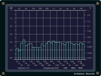
The first attachment below is the response of the speaker without felt. For an ESL the bass actually goes down fairly low, however that 50 hz peak adds a heck of a lot more bass that the music calls for. Boom town.
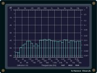
The second attachment is the response with felt. Except for the dip in the 100 to 250 range, the speaker has a more normal response, and a gradual decrease in the lower frequencies. The felt makes them sound much smoother too.
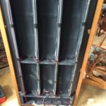
The third shows the felt applied to the back. I just used some tacky material spray my wife uses on her quilting projects. It is sticky but the felt can be removed easily if you don't like it. Ha, with the holidays, maybe I'll switch the black felt with some red.
Have fun whichever route you take.
Bondsan
I was having a heck of a time with the bass response of my stats; terrible booming that overshadowed whatever else bass the speaker was trying to reproduce. And as a visual bonus, they displayed a fairly entertaining light show during the evening hours.
I was extremely disappointed until Sy and Bolserst suggested applying inexpensive craft felt to the back stators. Hmmm. Tried the felt and it worked wonders. The bass is now clean, tight, and distinguishable, at least down to their workable frequencies. By damping the diaphragm, the felt also resolved almost all the the arcing and bottoming out issues. Bolserst can explain this much better in a technical manner.
The felt does dampen the rear sound very slightly, but as mentioned, probably no worse than a grill cloth or a little dampening if there is sound absorbing material on the rear wall. Lately I've been experimenting with removing sections of the felt from my top three panels. So far I can't decide whether with or without sounds better. Perhaps a tad bit brighter without the felt, but nothing to ponder on.
The first attachment below is the response of the speaker without felt. For an ESL the bass actually goes down fairly low, however that 50 hz peak adds a heck of a lot more bass that the music calls for. Boom town.
The second attachment is the response with felt. Except for the dip in the 100 to 250 range, the speaker has a more normal response, and a gradual decrease in the lower frequencies. The felt makes them sound much smoother too.
The third shows the felt applied to the back. I just used some tacky material spray my wife uses on her quilting projects. It is sticky but the felt can be removed easily if you don't like it. Ha, with the holidays, maybe I'll switch the black felt with some red.
Have fun whichever route you take.
Bondsan
Attachments
Thanks for your finding.....that's a lot of felt.....can we see the front?
The acoutats panels have felt...but now with the age..the felt is hard so it dose not eat to much of the top end...but puting wide paper tape were the felt is.... dose work same.. an can sound good...
The acoutats panels have felt...but now with the age..the felt is hard so it dose not eat to much of the top end...but puting wide paper tape were the felt is.... dose work same.. an can sound good...
Hi tyu,
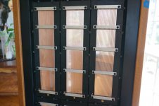
These are the same speakers in the 'progressively sized' thread. Below is a picture of the top three panels so you don't have search for them.
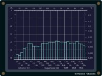
Just for the fun of it, I turned the speaker around and measured the felt side. The mic position was exactly the same; centered about half way up, three feet back. There is a slight roll off on the highs, but not sure how many people could hear it. My old ears have a hard time. Have know idea if this has any validity.
These are the same speakers in the 'progressively sized' thread. Below is a picture of the top three panels so you don't have search for them.
Just for the fun of it, I turned the speaker around and measured the felt side. The mic position was exactly the same; centered about half way up, three feet back. There is a slight roll off on the highs, but not sure how many people could hear it. My old ears have a hard time. Have know idea if this has any validity.
Attachments
Thanks agine for your pic an finding...
One thing I think gets over looket.....maybe not... the type of paper tape or pvc tape.. Can add it own sound when put on the panels.... adds a little crispness...to my ears to the top end.....felt seems too only removes highs....no matter how little..
Top end From ESls ...is the key to there great one of a kind sound...it seems to my ears all the notes...even deep bass.....start at the top end..
When one hears a pr of the big M1 Sound lab even in a live room....there topend darkness.. never ..sounds right to my ears..
look at these..i know were not talking diy esl here....an i am all about doing what you need to get the sound one wonts.....but adding ribbons...the amp see this speakers as a dead short.....no thanks...
all just one mans finding.....
Attachments
![1-1-1[1].jpg](/community/data/attachments/527/527498-1060a90b7a4cb06a4aae82534ea9fbcf.jpg?hash=EGCpC3pMsG)
Thanks Bolserst (#71) and Bondsan (#72) for this information. My experience has been with an underdamped conventional (vented) speaker, the Spendor BC1, which was a piece of freelance work by Spencer Hughes, still at the BBC at that time. This design was essentially late 1960s but came onto the English market in the early 70s. It didn't bother anyone at that time that the bass was "loose", as it has quaintly been described. I measured a Qts of 1.4 for this design in its original form. In the late 1970s Spendor lowered the box tuning, which brought down the Qts and reduced the excitation of box resonance around 140Hz. It sounded much better. However, when you take the speakers out of the box and just run them on their baffles as an open dipole the Qts drops to 0.7 and the bass really sounds clear and well defined.
As a result of this experience I wonder who has tried damping an ESL design further than with one layer of silk screen material? The tradition in ESL design has been to aim for a Q of around 2 for the first panel resonance, a preoccupation which appears (as I briefly review the situation) to have concentrated more on having as much bass response as possible rather than aiming for a specific quality of bass. There is an earlier comment by Capaciti on this (post #2 on http://www.diyaudio.com/forums/plan...ioning-vs-silicon-dots-resonance-control.html). However, he wished to avoid any damping materials near the diaphragms.
This leads me to the question: do we know of ESL designs where the damping was taken further so that a more damped bass (say Q = 0.7) results? I can only guess that this is achievable, but perhaps at the price of altering the quality of the sound.
I use two layers of mesh, one on each stator, to get the damping I want with readily available mesh. You could certainly use more resistive mesh to achieve Q=0.7, but remember the SPL of the mids and highs (ka>2) will be reduced. Basically the acoustic resistance of the mesh forms a "voltage divider" with the acoustic resistance of the air on both sides of the diaphragm (2ρc).… I wonder who has tried damping an ESL design further than with one layer of silk screen material? The tradition in ESL design has been to aim for a Q of around 2 for the first panel resonance…do we know of ESL designs where the damping was taken further so that a more damped bass (say Q = 0.7) results? I can only guess that this is achievable, but perhaps at the price of altering the quality of the sound
SPL reduction = 20*LOG[2ρc/(2ρc + Rmesh)]
See Eq(84) and associated text and figures in this Tim Mellow paper for more details.
http://www.mellowacoustics.com/articles/Membrane_in_free_space_and_baffle.pdf
mellowacoustics.com | acoustics soundfield and transducers
I have read that JansZen damps his diaphragms for critical damping alignment, but these are all hybrid designs. I am not aware of any full range ESLs that damp resonance below about Q=2. Another method you could use to adjust the Q of the resonance after application of some amount of acoustic damping is the Linkwitz Transform circuit, commonly used with dynamic woofers in sealed enclosures. That would make it possible to evaluate different Q values with the same bass extension.
Active Filters
Linkwitz Transform Subwoofer Equaliser
My understanding is that the fundamental resonance is typically left with a high-ish Q (such as 2 rather than 0.7) when the designer wants to use the increased output to compensate for the dipole losses in the bass.
Thanks Bolserst for #77. Your post #65 where you showed how 0.4 spacing augments 40 rayl resistance = 100 rayls provided a fine introduction to the 100 rayl resistance used in Mellow's Fig. 10. Without this it would have been harder to connect the practice of one layer of silk screen to Mellow's article.
On the Linkwitz transform (the link: Aktive Filters). Linkwitz writes in his example "correcting for a woofer with peaked response (Qp = 1.21) and early roll-off (Fp = 55 Hz), to obtain a response that is 6 dB down at 19 Hz and with Q = 0.5" Surely what he means is that the resulting response has that which would be given by a woofer with Q = 0.5. From my understanding we do not reduce the mechanical resistance of the woofer with such a filter, merely change the amplitude response as if the circuit had a Q of 0.5. Is not the impulse response of the woofer unchanged? Or do I have to learn something about oscillating circuits? (I have no engineering training).
On the Linkwitz transform (the link: Aktive Filters). Linkwitz writes in his example "correcting for a woofer with peaked response (Qp = 1.21) and early roll-off (Fp = 55 Hz), to obtain a response that is 6 dB down at 19 Hz and with Q = 0.5" Surely what he means is that the resulting response has that which would be given by a woofer with Q = 0.5. From my understanding we do not reduce the mechanical resistance of the woofer with such a filter, merely change the amplitude response as if the circuit had a Q of 0.5. Is not the impulse response of the woofer unchanged? Or do I have to learn something about oscillating circuits? (I have no engineering training).
Last edited:
Basically the acoustic resistance of the mesh forms a "voltage divider" with the acoustic resistance of the air on both sides of the diaphragm (2ρc).
SPL reduction = 20*LOG[2ρc/(2ρc + Rmesh)]
Just wondering if you could help a math dummy like me understand this 🙂....
So I tried reading thru that paper and after weeping at the loss of all the calculus I've forgotten, I'm trying to figure what the value of the pc (acoustic resistance of air) would be?
I would hazard a guess that it is the speed of sound in air @ 20C = 343.21 m/s * the density of air 1.2041 kg/m3 which equals 413.25???? Am I way off base?
Last edited:
- Status
- Not open for further replies.
- Home
- Loudspeakers
- Planars & Exotics
- Another segmented ESL