Hi,
I rather thought of pure clear acrylics with a printed-on layer of conductive transparent ink and sealed with an transparent insulative coating/laquer. The membrane could be transparent as well as the membrane coating. The stators could be routed from acrylic sheets and heat treated after to get the matted surfaces clear again and the sharp edges rounded, or it may even be better cast into a mould, thereby allowing to include spacers and stiffening ribs at the same. The conductive ink may be printed on with standard inkjet printer technology. There are several different formulations over a certain ohmic range. Lowohmic inks may be used as replacement for cabling and copper charge ring. A special transparent laquer, commonly used for insulating and sealing PCBs may be used as insulative layer also. It may be possible to replace the insulative coating by a second cast of acrylics, thereby sealing the conductive areas completely within the stator structure.
If not cast into the stator structure, 3M's clear transparent tapes may be used as spacers. The mounting frame may of course be made from standard acrylic material again. So all is there ... the idea, the materials an the technologies. The only thing I'm still missing ...... and that's the point You Gerald my friend, come into play, are transparent toroids
jauu
Calvin
The designers of the new Essence ESL must have read your post above, as they are pretty much exactly as you described.
Are you talking about the new ESLs recently announced in the Essence blog? It looks like an interesting speaker and I would be very interested in getting further information about it. The low frequency extension is very good for an ESL with such a small surface area. The price is also very good.The designers of the new Essence ESL must have read your post above, as they are pretty much exactly as you described.
Last edited:
Are you talking about the new ESLs recently announced in the Essence blog? It looks like an interesting speaker and I would be very interested in getting further information about it. The low frequency extension is very good for an ESL with such a small surface area. The price is also very good.
I didn't know about the Essence Blog... I read about them in a thread on the Audio Circle Forum here
And yes, their direct marketing price is unbeatable. That said; it seems heretical for self-respecting DIY'ers to actually buy a speaker, lol.
... I discovered that the symmetric version of this ESL has some additional magic – a polar response that varies as a second-order Butterworth response versus angle – that means (i) a broad listening area near the on axis position, (ii) no zeros and phase reversals in the frequency response (causing the phasiness that wide-segment ESLs are known for) and (iii) a graceful decrease in treble as the listener moves of axis. The results of the study were published in JAES as “A wide range electrostatic loudspeaker with a zero free polar response”. Contact me if you want a pre-print.[/FONT][/SIZE]
Question: Is the "symetric" version the one where the central segment width is 2X the surrounding segments? I take it from this that the asymetric version would not offer the "additional magic" you described?
And could you please expand your explanation a bit regarding the "additional magic" with the symetric version, in layman's terms that a dummy like me might understand?
Thanks,
Charlie
Last edited:
The designers of the new Essence ESL must have read your post above, as they are pretty much exactly as you described.
i was thinking about the same
") for a while. although low resistance coating would be expensive. indium tin oxide. for instance. but of course graphene is on its way... and as well very expensive still.
for a while. although low resistance coating would be expensive. indium tin oxide. for instance. but of course graphene is on its way... and as well very expensive still.I believe both configurations with 1X width or 2X width central segment surrounded by symmetric arrangement of remaining segments qualify for "symmetric" version magic.Question: Is the "symetric" version the one where the central segment width is 2X the surrounding segments?
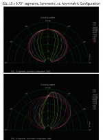
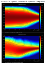
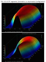
I’m sure golfnut will jump in soon enough, but I just happened to be cleaning up some old simulation files and ran across these directivity comparisons I created several years ago that may help answer your question. The “magic” of the symmetric configuration is evident by the broad smoothly trending polar response. By comparison the asymmetric configuration results in narrowing, peaking, and shifting of the main polar lobe as frequency increases.And could you please expand your explanation a bit regarding the "additional magic" with the symmetric version, in layman's terms that a dummy like me might understand?
Note that the comparisons are for the same segment size and number of segments.
Atttachments 1: Comparison of Directivity Polar for Symmetric .vs. Asymmetric Segmentation
Atttachments 2: Comparison of Waterfall Polar Response for Symmetric .vs. Asymmetric Segmentation
Atttachments 3: Comparison of Sonogram for Symmetric .vs. Asymmetric Segmentation
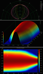
Atttachments 4: Directivity Polar, Response, & Sonogram for un-Segmented ESL
Atttachments 5: Directivity Polar, Response, & Sonogram for Asymmetric Segmented ESL
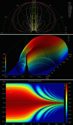
Atttachments 6: Directivity Polar, Response, & Sonogram for Symmetric Segmented ESL
Attachments
-
 ESL_Sym-vs-Asym_Polar.png261.6 KB · Views: 469
 -
ESL_Seg_Directivity_Summary.pdf492.8 KB · Views: 143
-
 ESL_Directivity_Segmented-Sym.png433.3 KB · Views: 146
 -
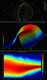 ESL_Directivity_Segmented-Asym.png452.8 KB · Views: 449
 -
 ESL_Directivity_Unsegmented.png510.2 KB · Views: 455
 -
 ESL_Sym-vs-Asym_Sonogram.png493.6 KB · Views: 452
 -
 ESL_Sym-vs-Asym_Waterfall.png468.1 KB · Views: 468
Last edited:
Hi Charlie
Re additional magic of symmetric segmented ESL....
I'm sorry I cant think of a really simple explanation, though Bolserst gives a really nice summary of the results.
The essence of the problem is phase differences between sound waves coming from different parts of the diaphragm. Keep in mind that the wavelength of sound at 10 kHz is about 30 mm.
If one part of the diaphragm is half a wavelength closer or further from the listener than another part of the diaphragm, then the two waves will cancel.
These cancelation effects become apparent at high frequency where the wavelengths are shortest. The effects are also most apparent off axis where the differences in distance between the middle and the edges of the panel are greatest. It also turns out that abrupt edges in the radiation pattern also cause ripples.
So the ideal ESL is very narrow at high frequencies to avoid these effects, and wide at low frequencies so it can produce sufficient bass SPL.
If you think of the segmented ESL as a sequence of low-pass RC filters you can see that it achieves this ideal. At high frequencies, most of the sound comes from the central segment. As the frequency falls, the radiation pattern gradually spreads out until at low frequencies the whole panel radiates. Also, there is a gradual progression from high to low output on both sides of the panel = no abrupt edges in the radiation pattern.
hope this makes sense
Rod
Re additional magic of symmetric segmented ESL....
I'm sorry I cant think of a really simple explanation, though Bolserst gives a really nice summary of the results
.The essence of the problem is phase differences between sound waves coming from different parts of the diaphragm. Keep in mind that the wavelength of sound at 10 kHz is about 30 mm.
If one part of the diaphragm is half a wavelength closer or further from the listener than another part of the diaphragm, then the two waves will cancel.
These cancelation effects become apparent at high frequency where the wavelengths are shortest. The effects are also most apparent off axis where the differences in distance between the middle and the edges of the panel are greatest. It also turns out that abrupt edges in the radiation pattern also cause ripples.
So the ideal ESL is very narrow at high frequencies to avoid these effects, and wide at low frequencies so it can produce sufficient bass SPL.
If you think of the segmented ESL as a sequence of low-pass RC filters you can see that it achieves this ideal. At high frequencies, most of the sound comes from the central segment. As the frequency falls, the radiation pattern gradually spreads out until at low frequencies the whole panel radiates. Also, there is a gradual progression from high to low output on both sides of the panel = no abrupt edges in the radiation pattern.
hope this makes sense
Rod
Hi Charlie
It occurs to me that some might appreciate a technical description of the origin of polar response effects....
It turns out that the far-field response of an ESL is related to the Fourier transform of the stator current distribution.
The single segment ESL, which has the same stator current over the whole area, has a polar response given by the Fourier transform of a rectangle, which consists of two different sinc functions (sinc = sin(x)/x function) - one in vertical direction, one in horizontal direction. This gives the very narrow pattern with lots of lobes that you can see in Bolserst's figure for the unsegmentred ESL. The result is the classic head-in-a-vice ESL with a sweet spot that is often narrower than the listeners head.
For the symmetric line-source segmented ESL using the RC transmission line, the stator current distribution has the central segment at full current and an exponential decay in current either side (left and right). The Fourier transform in this case is the second-order Butterworth. AS you can see from Bolserst's pictures, the sweet spot is much wider and there are no lobes. Note that the line source should ideally be infinitely tall to avoid the lobing effects in the vertical direction. If the ESL is tall enough, the reflections off the floor and ceiling do this for you.
For the Quad ESL-63 family of ESLs, Walker attempted to simulate a point source, for which the Fourier transform is an infinite plane - i.e. perfect polar response. Unfortunately, commercial imperatives and the limited number of circular segments means that they perform OK only near the centre of the polar pattern. As close as 15 degrees of so off axis, there are holes in the response at some frequencies (see the Quad datasheets), probably caused by phase reversals and cancelations due to the finite segment widths.
hope this helps
Rod
Hi Charlie
It occurs to me that some might appreciate a technical description of the origin of polar response effects....
It turns out that the far-field response of an ESL is related to the Fourier transform of the stator current distribution.
The single segment ESL, which has the same stator current over the whole area, has a polar response given by the Fourier transform of a rectangle, which consists of two different sinc functions (sinc = sin(x)/x function) - one in vertical direction, one in horizontal direction. This gives the very narrow pattern with lots of lobes that you can see in Bolserst's figure for the unsegmentred ESL. The result is the classic head-in-a-vice ESL with a sweet spot that is often narrower than the listeners head.
For the symmetric line-source segmented ESL using the RC transmission line, the stator current distribution has the central segment at full current and an exponential decay in current either side (left and right). The Fourier transform in this case is the second-order Butterworth. AS you can see from Bolserst's pictures, the sweet spot is much wider and there are no lobes. Note that the line source should ideally be infinitely tall to avoid the lobing effects in the vertical direction. If the ESL is tall enough, the reflections off the floor and ceiling do this for you.
For the Quad ESL-63 family of ESLs, Walker attempted to simulate a point source, for which the Fourier transform is an infinite plane - i.e. perfect polar response. Unfortunately, commercial imperatives and the limited number of circular segments means that they perform OK only near the centre of the polar pattern. As close as 15 degrees of so off axis, there are holes in the response at some frequencies (see the Quad datasheets), probably caused by phase reversals and cancelations due to the finite segment widths.
hope this helps
Rod
Thanks for helping me understand this Rod,
I do OK with mechanics but not so much with electronics.
I’ve heard (read of) the resistor network described as a “delay line”, so I had envisioned it sequentially attenuating both frequency and time/phasing. And each step would attenuate the HF downward another 6db/octave (?). BTW, I would love to understand how varying resistor values would affect the attenuation.
Even though I can’t hear much past 5Khz, I have a fetish for treble so I want to know that whatever segmentation arrangement I might use would retain really good treble response.
Assuming the panel’s frequency response (dipole roll off aside) would be approximately flat with no segmentation (is that a valid assumption?), I’m struggling to grasp how a series of low pass filters would not so restrict treble output as to render the frequency response unbalanced toward the bass end. Am I correct in assuming the energy loss at each downward step is what keeps the frequency response balanced?
I’m asking a lot of questions because I want to build new panels for my old beam splitter hybrid speakers—this time using PVC insulated copper wires mounted on an esthetically pleasing wooden ladder frame.
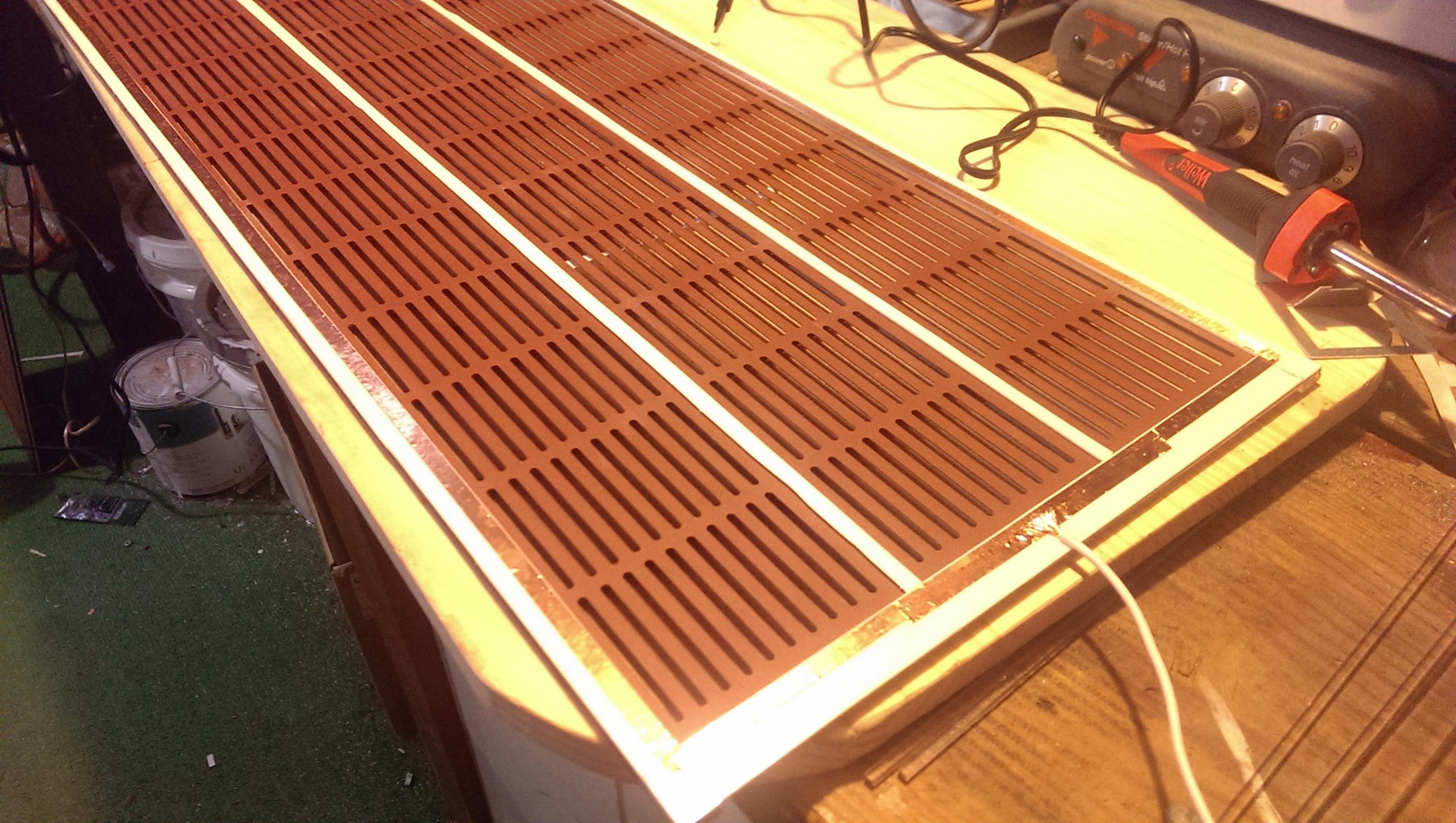
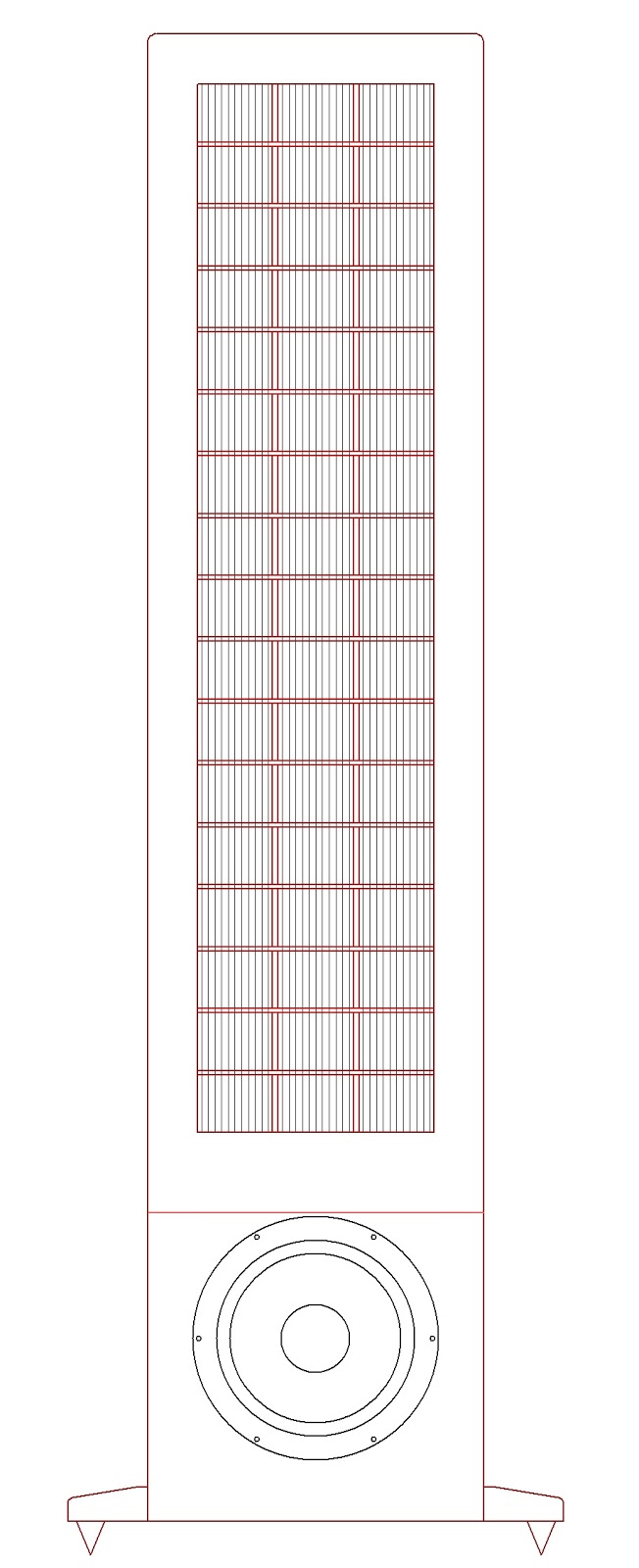
So I am drawing up two panel designs to fit my speakers’ 10.5” x 46.5” panel openings, and then choosing the best compromise between performance and esthetics. The two designs differ in that one segments the diaphragm vertically and the other horizontally.
The first design would be very much like JamesThomas128’s panels shown in the first image below, with respect to sectioning the diaphragm. The second image is a sketch of my existing hybrid speaker with a red oak grid supporting the wires and 3 vertical diaphragm sections. For some reason this sketch shows up squashed here but it opens up correctly if you mouse click on it.
Perhaps the biggest question and decision I still have to make is whether to use the segmentation scheme where the width of the center segment = 2x the other segments or the scheme where all segments are same width.
Unfortunately I don’t yet understand the sonic differences or the pros/cons between these two configurations so I’m hindered in making a decision.
Hi Charlie
If you look back in earlier posts on this thread, you'll see that the segmented line source has a natural frequency response that is compensated, almost exactly, by the RC transmission line.
If you go to wireesl.weebly.com/links you'll find a copy of the paper I wrote a number of years ago - it gives the design equations, Baxandall's paper is also there- it gives some of the background to my paper.
The RC transmission line is not a delay line. The true delay line is the LC transmission line, which walker used for the Quad ESLs.
regards, R
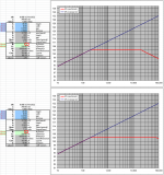
You may recall from the Segmented ESL spreadsheet calculator (based on golfnut's AES paper) that the natural response of an ESL line source is not flat, but increases with frequency sloping up at +3dB/octave. This is the blue line shown in the plot in the spreadsheet.(Attachment #1) The resistor values determined by equations from golfnut’s AES paper result in a flat response from the chosen low frequency limit fL, and extending to an upper limit fH which is dependent on the number of segments you choose. You are correct that the progressive loss of high frequency energy as you move from segment to segment is what keeps the response balanced. Note however, that the resulting dispersion “is what it is”. You cannot independently manipulate the dispersion without affecting the flatness of the response, or manipulate the response without affecting the dispersion.…Even though I can’t hear much past 5Khz, I have a fetish for treble so I want to know that whatever segmentation arrangement I might use would retain really good treble response. Assuming the panel’s frequency response (dipole roll off aside) would be approximately flat with no segmentation (is that a valid assumption?), I’m struggling to grasp how a series of low pass filters would not so restrict treble output as to render the frequency response unbalanced toward the bass end. Am I correct in assuming the energy loss at each downward step is what keeps the frequency response balanced?
A few links to jog you memory on these topics:
http://www.diyaudio.com/forums/plan...-segmented-wire-stator-esl-3.html#post4183068
http://www.diyaudio.com/forums/plan...-segmented-wire-stator-esl-9.html#post4192859
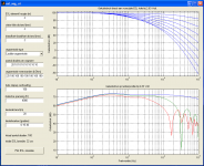
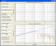
Also, remember that the “esl_seg_ui” calculator provides a plot(upper) showing the drive signal reaching each segment so you can get a feel for how high frequencies are progressively filtered out.(Attachment #2) If you set all the resistors to low values you effectively have an un-segmented panel and you will see the +3dB/oct slope in the on-axis response.(Attachment #3)
http://www.diyaudio.com/forums/plan...r-esl-simulator-esl_seg_ui-8.html#post3960276
Attachments
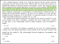
Charlie, I suspect that it is knowledge of acoustics, rather than electronics that is an impediment to understanding directivity control. Whilst waveguides, horns and exploiting dipole radiation are methods of controlling directivity we should never lose sight of the most important factor of all which is the acoustic size of the radiating surface. Acoustic textbooks call this the ka factor. A rigid disc of 344mm diameter radiating 1kHz has a ka factor of one. 344mm is the wavelength of 1kHz in air, thus the disc is one wavelength (symbol lamda) in size. At 10kHz this same disc has a ka of 10 because the wavelength has shrunk to 34.4mm. At 100 Hz ka becomes 0.1 as the wavelength has grown to 3.44 metres or ten times the size of the disc.Thanks for helping me understand this Rod,
I do OK with mechanics but not so much with electronics.
Generally small sources have broad radiation patterns and large sources narrow patterns. Large or small needs to be thought of in terms of ka rather than what a tape measure is telling us. You seem to be asking the question "If the radiation area is shrinking towards higher frequencies won't this affect the frequency response?" It depends on what is meant by frequency response; whether on axis, or over a range of listening/measurement angles. Herein lies the nexus between acoustic size and directivity. When the radiating area is several wavelengths in size one part of it interferes with another part, particularly when there is a half wavelength difference in distance to the listener when complete cancellation can occur. Conversely radiation from different areas can sum to produce peaks. This is why large planar diaphragms have a very 'fingered' pattern at high frequencies.
So the answer to your question is that the frequency response will be affected, but for the better, as in the horizontal plane, the membrane will no longer be interfering with itself. Another query you have is about time delays as well as attenuation between segments as we move outwards from the centre. Golfnut has probably commented on this, if not here certainly in his AES paper which I have read but do not have readily to hand.
Sorry if I am mentioning things you already know.
Keith
Last edited:
…A rigid disc of 344mm diameter radiating 1kHz has a ka factor of one. 344mm is the wavelength of 1kHz in air, thus the disc is one wavelength (symbol lamda) in size. At 10kHz this same disc has a ka of 10 because the wavelength has shrunk to 34.4mm. At 100 Hz ka becomes 0.1 as the wavelength has grown to 3.44 metres or ten times the size of the disc…
Your description of how radiator size affects radiation pattern is a good addition to the discussion. Thanks!
Just wanted to clarify that for ka=1 @ 1kHz the disc diameter would be 109mm.
(344mm is off by a factor of ᴫ=3.1416)
k = 2ᴫf/c (f=frequency, c=speed of sound)
a = radius of circular piston
d = diameter of piston = 2a
λ = wavelength = c/f
ka= 2ᴫfa/c = ᴫ(2a)(f/c) = ᴫd/λ
So, for 1khz where λ = 344mm: ka = ᴫd/λ = ᴫd/344 = 1
Solving for d:
d=344/ᴫ = 344/3.1416 = 109mm
Thanks Bolserst: you expose the folly of writing on subjects not fully understood. I have the original Beranek plus the latest Beranek and Tim Mellow versions of "Acoustics" and yes, it is the circumference that gives rise to the ka number.
Probably been reading many mentions of acoustic size in terms of wavelength and assumed wavelength and ka to be interchangeable terms.
Keith
Probably been reading many mentions of acoustic size in terms of wavelength and assumed wavelength and ka to be interchangeable terms.
Keith
Probably been reading many mentions of acoustic size in terms of wavelength and assumed wavelength and ka to be interchangeable terms.
Attached is an excerpt I found helpful for understanding what the wave number "k" represents.
Basically it is the spatial equivalent of frequency. (ie cycles per distance rather than cycles per second)
Reference:
Loudspeaker and Headphone Handbook, J. Borwick, Ed.
(Reed Educational and Professional Pub., Woburn, MA,
1998), pp. 3 – 4
Attachments
This is a great discussion!!!
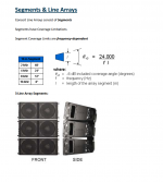
Quite a while back I was reseaching this stuff and I wanted to know the formula that shows the relationship between ka and the dispersion angle for a frequency.
Then I stumbled upon this paper,
http://www.proaudio-central.com/files/2015-09/line-arrays-part-i-designing-and-deploying-qsc.pdf
On Page 6 it shows a very simply formula for this.
I had used this formula to painstakingly plot out a function manualy and compared it to FRD Consortium spreadsheet that does this as well and seems fairly accurate.
I had posted a links to these pages before and also the very useful spreadsheets but they keep getting moved.
I have all of the spreadsheets I believe, and if anyone wants them I would gladly make a ZIP file to send to anyone.
Or I could post it here if it is okay without breaking any rules since they are getting hard to obtain and move around a lot.
They are what I used to predict my Segmented Desktop ESL design at ESLDIY, but sadly all of those pictures have not been restored yet.
I still have them all but they are scattered in my archives at the moment, Sorry or else I would repost them here.
Anyhow this time I have made a screenshot of page 6 to post here for safe keeping.
Cheers!!
jer
P.S. I just located the link for spreadsheets,
http://www.rjbaudio.com/Audiofiles/FRDtools.html
The FRD link is broken and the spreadshet I used "Asymmetrical Response
Pattern Estimator" is found here,
http://alloy.wishray.com/frd/frdgroup.htm
Attachments
Last edited:
Bolserst, you have an uncanny ability to sense that people such as me are missing something in understanding a concept, yet manage to steer us in the right direction in a non judgemental way!
Maybe Beranek could have been more helpfull by devoting a paragraph to explaining the ka factor; instead, we have the wave number mentioned on P26. It is not untill P102 that we see it multiplied by the radius of a piston, a, to become the ka factor.
In the new Beranek/Mellow edition P32 things improve somewhat when they mention "When k is multiplied by a characteristic dimension such as the length of a tube or the radius of a circular radiator, it forms a dimensionless parameter that is proportional to frequency"
Pi being relevant to both angular velocity and the geometry of circular disks has the potential to muddy the waters, I can now see.
Keith
Golfnut, although the post is 3 years old, this reply shows how interesting the topic is! May I ask what you what now implement instead of the assymetrical layout of the treble/bass sections? I have been working towards making an electrostatic (which I wanted to do years ago) and recently had the interesting experience of running my Spendor BC1 speakers as dipole baffles. What I discovered was the significance of diffraction correction for stereo imaging. Of course, any assymetrical layout will have an assymetrical polar response, but might otherwise be useful for controlling diffraction - at least that is my current perspective.
Hi ENCR
I have thought about a number of options, but a simple option is an RC transmission line with maybe 39 segments (10-15 mm wide) arranged in three vertical sections of 13 segments each and the same width. The transmission line is driven at the central segment of the middle section. The design would require a largish PCB perhaps 450 mm wide and 600 mm long - but within the capability of most PCB makers. The membrane would be glued to ~ 10 mm wide spacers separating each section and to spacers on the outside edge of the PCB. The central section, would then carry the midrange-treble-bass, and the outer two sections essentially bass only. The T-line resistors would be 1W high voltage surface mount and soldered directly to the copper on the PCB, which would face outwards in the final assembly.
Any number of stators can be stacked as required - the resistor values stay the same for a given frequency response! Three stator sections tall = 1.8m + perhaps 100 mm for frame and pedestal, would be a good size for a home full-range ESL. Two sections =1.2 m good for a hybrid. Maximum overall width turns out to be about 500 mm. Any wider and lobes start appearing in the polar response.
hope this helps
- Status
- This old topic is closed. If you want to reopen this topic, contact a moderator using the "Report Post" button.
- Home
- Loudspeakers
- Planars & Exotics
- Another segmented ESL