DIY 2+2s: I'm planning on making my own frames to make 2+2s out of Model 4s and was wondering if anyone has done this before and how did you arrange the panels? I was thinking of stacking the 8" panels inboard and the 9" panels outboard at a 9 degree angle between the stacks, each speaker a mirror image of the other, of course. My reasoning is to put the "high frequency" ones in the middle which would be pointed directly at the listener.
I understand the different panel widths were to reduce combing effects at low frequencies, so would a checker-board arrangement make more sense? Or is the vertical interaction too minimal to worry about? Also, if anyone has any kind of plans or pictures of DIY 2+2s, I'd be most grateful for any input.
I understand the different panel widths were to reduce combing effects at low frequencies, so would a checker-board arrangement make more sense? Or is the vertical interaction too minimal to worry about? Also, if anyone has any kind of plans or pictures of DIY 2+2s, I'd be most grateful for any input.
These were just posted on Audiogon:
Acoustat 1+1 Red Medallion | Planars | Bon Air, Virginia 23235 | Audiogon
Wish I lived over on that side. What a deal!
Acoustat 1+1 Red Medallion | Planars | Bon Air, Virginia 23235 | Audiogon
Wish I lived over on that side. What a deal!
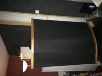
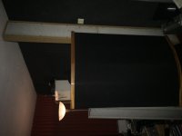
I have placed the most inward panels facing each other ( not 100% but almost) this gives me the most realistic image. I have found it accidently as my tv is behind the panels and they are blocking the view. At this moment i use 7 panels on each side ( i need to build a new frame as well using 8 panels).
If you have 4 panels per side then i would not stack them all but 2, close the left over space for better bass and it will look better as well. Do not angle them too much in this case as you will get “holes” when moving your head. In this case you will get 3 panels width esl’s . If you have the space add extra “wooden” panels on each side for even better bass response.
Last edited:
I have placed the most inward panels facing each other ( not 100% but almost) this gives me the most realistic image. I have found it accidently as my tv is behind the panels and they are blocking the view. At this moment i use 7 panels on each side ( i need to build a new frame as well using 8 panels).
Hi Lampie
The arrangement you describe sounds a bit like the Robertson-Aiken layout using Quad ESL63 pairs.
Would you be able to provide a sketch, or photo to show this layout?
Cheers
Grant
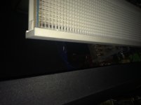
Some pictures:
Ah understood.
Do you run all panels full range?
Quite an array there with Model 4's, 1+1's and that tricky little 7th panel.
I am looking to run split pairs from model 4's, a front facing pair, positioned like your model 4's, running full range and the second pair, bass only, positioned like you have your single inner edge panel.
Cheers
Grant
Last edited:
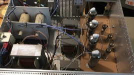
Yes, full range all panels. The OTL has no problems driving all and could even handle more. I have build it 15 years ago and use it on a daily basis. As the panels are balanced by nature my entire system is balanced from the D/A converter on. No phase inverters used (4 mono channels). For me it gives the cleanest sound and life experience so far.
Attachments
Thanks for the replies. Wow, WAF off the charts (in a bad way.) Interesting ideas. If I understand correctly Lampie519, "not stacking all but 2" means the equivalent of a Model 2 adjacent to a 1+1? And if you close off the space, it would be like a Model 6?
Last edited:
The Medallion transformer upgrade was available in the mid-1980s and replaced both the LF and HF transformers with transformers with better inter-leaved windings with superior sonics. It was around a US$600 upgrade that was factory installed by shipping your interfaces to the factory. A blue sticker was put on the interface to indicate the upgrade. A little later, the C-mod was incorporated which changed the "crossover" and impedance matching of the HF transformer which lowered the distortion by allowing less LF signal into the HF path. This was combined with the Medallion transformer upgrade and a red sticker was applied to the interface. There's lots more information on this thread if you search.
Right, the panels were unchanged, but they did change to 5-wire from 3-wire at some point for better charge distribution. Here's the "C-mod" schematic and instructions:
https://www.diyaudio.com/forums/att...-1865592-acoustat-esl-panels-interfaces-1-jpg
https://www.diyaudio.com/forums/att...230-acoustat-answer-acoustat-mod-rev-2018-pdf
https://www.diyaudio.com/forums/att...-1865592-acoustat-esl-panels-interfaces-1-jpg
https://www.diyaudio.com/forums/att...230-acoustat-answer-acoustat-mod-rev-2018-pdf
Last edited:
In this case i cannot be of help really as i do not have any experience adding panels to transformers. My guess would be to place the HF panels more inward and add only LF panels left and right. So you have only one line source with HF per side (left and right). In this case you could stack the units with the 5 wires.
When I referred to the "high frequency" panel, I meant the 8" which has a slightly higher resonant frequency than the 9". I think the design intent of different widths was to prevent excessive combing effect. They're really all full range and the HF output is probably almost identical, but I'd imagine that the 9" panels have a little better bass extension. In the Spectras, they ran portions of the panels as high, mid and/or low.
I also have 2 different panel sizes ( same as yours just 3 wires each). In my case the smaller once are in the middle side by side in the model 4’s and all the rest is wider. I also would like to stack the snaller panels to create a 6 panel model 3 version. Then 2 more that face each other as explained earlier. I have all the panels in house just not the place and energy to start on it now. It is on my todo list (as so many things).

- Home
- Loudspeakers
- Planars & Exotics
- Acoustat Answer Man is here