LuFo doesn’t need matched JFETs. Taking two consecutive of a tape roll is close enough for similar left and right channels. If you do SuSyLu then needs to be matched. It’s more complicated than sticking in transistor tester. Please see the GB thread for how.
Hi X,
I am wondering if I bought the correct parts from a store on Ali Express. The LU1014D transistor was advertised as an N-channel Mosfet, not an N-channel Jfet. It never really occurred to me that their could be variations, I just looked for Lu1014D transistors.
If I put it in a tester, it may tell me whether it is a Mfet or Jfet?
MM
If it is a LU1014D, it is a power JFET. From the measurements made by Woofertester, the behavior appears to be consistent with a SIT.
Thanks X,
I tested a few in my transistor tester and they came up as Jfets, so OK there. It showed me values of I around 2.0mA and Vgs around 1.4V.
MM
I tested a few in my transistor tester and they came up as Jfets, so OK there. It showed me values of I around 2.0mA and Vgs around 1.4V.
MM
Final Manufacturing Files for LuFo
As promised, here are the complete manufacturing files for the LuFo amp with all known errors corrected. The amp has been verified by both Vunce and myself and has also been used as the basis for the SuSyLu amp (you will need 4 boards for a stereo SuSyLu). I would like to express my sincere thanks to JPS64 for providing a superb state of the art layout that is a work of art. I would also like to thank Vunce for building the first verification build of the LuFo.
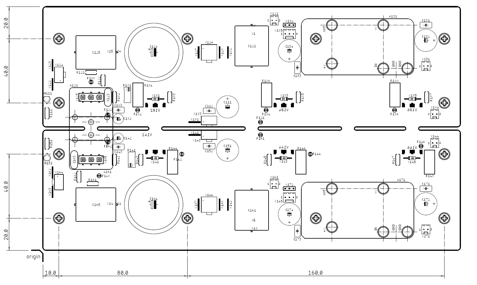
The LuFo has provision for an on-board Yarra/M2X daughterboard as a front end. Choices include the Melbourne or Aksa Lender if you want to hit the 50Vpp required to produce 39w into 8ohms. You can also use an externally mounted preamp of your choice. A Pass ACP+ or Wayne's Burning Amp 2018 peamp might also work well with some mods to achieve higher voltage swing. Adventurous people might try to use the front end from the DIYA Lottery VFET amp. If you have a Yarra with Melbourne or an Aksa Lender all boxed up and ready to go then that works well too. In order to use the on-board Aksa Lender, you will need to build the new Aksa Lender double decker board designed specifically for the LuFo with its own built in DC-DC booster circuit. This will be posted separately. Alternatively, if you are not opposed to opamp based front ends, the OPA454 version will also be made available and works really well - that is the current one I am using.
The PCB follows the DIYA store UMS heatsink format - a 4U to 5U x 300mm UMS heatsink chassis should work fine. Total thermal output will be about 85W per channel. For SuSyLu, double that.
The amp is a relatively simple build with very few parts. You will need a handful of N channel TO-247 MOSFETs, and a pair of LU1014D or LD1014D JFET mounted on the IMS adapter from the GB by WG45.
For power supplies, a CRCRC using 15,000uF 50v caps (first one rated for 8A ripple current, high ESR), and 0.22R 5W resistors. Or a cap multiplier based PSU to provide the lowest ripple.
The attached files include:
- Schematic diagram
- BOM in Excel format
- PDF Stuffing diagrams (top and bottom)
- PDF PCB dimension diagram
- Gerber files
The files are free for DIY use, and are not for commercial use. For those who do not want to order their own boards, I am starting a LuFO PCB GB interest thread here.
I hope you give this amp a shot - it is very simple and sounds superb. 39w is a nice amount of power too.
You need to find a circa 60mH 0.5ohm DCR inductor. Hammond, Lundhal, etc or MOTs.
If you feel brave, try making the SuSyLu for a 100w Class A amp.
Thank you JPS64 for making this available to the DIYA community!

As promised, here are the complete manufacturing files for the LuFo amp with all known errors corrected. The amp has been verified by both Vunce and myself and has also been used as the basis for the SuSyLu amp (you will need 4 boards for a stereo SuSyLu). I would like to express my sincere thanks to JPS64 for providing a superb state of the art layout that is a work of art. I would also like to thank Vunce for building the first verification build of the LuFo.
The LuFo has provision for an on-board Yarra/M2X daughterboard as a front end. Choices include the Melbourne or Aksa Lender if you want to hit the 50Vpp required to produce 39w into 8ohms. You can also use an externally mounted preamp of your choice. A Pass ACP+ or Wayne's Burning Amp 2018 peamp might also work well with some mods to achieve higher voltage swing. Adventurous people might try to use the front end from the DIYA Lottery VFET amp. If you have a Yarra with Melbourne or an Aksa Lender all boxed up and ready to go then that works well too. In order to use the on-board Aksa Lender, you will need to build the new Aksa Lender double decker board designed specifically for the LuFo with its own built in DC-DC booster circuit. This will be posted separately. Alternatively, if you are not opposed to opamp based front ends, the OPA454 version will also be made available and works really well - that is the current one I am using.
The PCB follows the DIYA store UMS heatsink format - a 4U to 5U x 300mm UMS heatsink chassis should work fine. Total thermal output will be about 85W per channel. For SuSyLu, double that.
The amp is a relatively simple build with very few parts. You will need a handful of N channel TO-247 MOSFETs, and a pair of LU1014D or LD1014D JFET mounted on the IMS adapter from the GB by WG45.
For power supplies, a CRCRC using 15,000uF 50v caps (first one rated for 8A ripple current, high ESR), and 0.22R 5W resistors. Or a cap multiplier based PSU to provide the lowest ripple.
The attached files include:
- Schematic diagram
- BOM in Excel format
- PDF Stuffing diagrams (top and bottom)
- PDF PCB dimension diagram
- Gerber files
The files are free for DIY use, and are not for commercial use. For those who do not want to order their own boards, I am starting a LuFO PCB GB interest thread here.
I hope you give this amp a shot - it is very simple and sounds superb. 39w is a nice amount of power too.
You need to find a circa 60mH 0.5ohm DCR inductor. Hammond, Lundhal, etc or MOTs.
If you feel brave, try making the SuSyLu for a 100w Class A amp.
Thank you JPS64 for making this available to the DIYA community!
Attachments
Last edited:

Hi xrk,
I like it.
Regarding inductor, could this one be used? https://www.mouser.at/datasheet/2/177/153_159-736947.pdf (Hammond 60 mH 700 mohms)
I like it.
Regarding inductor, could this one be used? https://www.mouser.at/datasheet/2/177/153_159-736947.pdf (Hammond 60 mH 700 mohms)
Hi xrk,
maybe it's just me, but there are two resistors in the BOM with a value of 0R0. Could you explain it please?
maybe it's just me, but there are two resistors in the BOM with a value of 0R0. Could you explain it please?
Correct, R122 and R162 as you could see in the schematics. It´s layout technically necessary. Please, be free, use wire.
JP
JP
Hi xrk,
could you please take a look at this? LuFo Amp - 39w SE Class A from 28v Rail
The 159ZC seems to be right, but I would need you advice.
Thank you.
could you please take a look at this? LuFo Amp - 39w SE Class A from 28v Rail
The 159ZC seems to be right, but I would need you advice.
Thank you.
Hi xrk,
I like it.
Regarding inductor, could this one be used? https://www.mouser.at/datasheet/2/177/153_159-736947.pdf (Hammond 60 mH 700 mohms)
The 159zc could possibly work. It’s 2A current us a bit less then nominal 3A and 0.7ohm dcr is s hit high. Probably close enough though.
Thank you xrk! The difference regarding current is 50%, so this would be too risky for me, I will look for another solution. Maybe a custom built one.
Having more inductance rating (mH) is not a problem. 60mH was just suggested as a minimum and even 50mH can work. The inductance is frequency dependent and is reported as an average or at a specific frequency. Often, it is reported at 10kHz, thus the value near 50Hz where you want it to be a larger value can be in the 200mH range if it is 60mH near 10kHz. This is good. The low DCR is important - >> 1ohm doesn’t work as there will be too much dissipation in the coil from heating.
@woody: input capacitance of the LuFo amp or the inductor?
@woody: input capacitance of the LuFo amp or the inductor?
Last edited:
- Home
- Amplifiers
- Pass Labs
- LuFo Amp - 39w SE Class A from 28v Rail