Yes, and just note that the output power of the LuFo is going to depend on the voltage swing if the preamp as it has no gain. So, sort of like an F4.
To get 40w into 8ohms requires 17.9Vrms or 51Vpp. Is the BA-3 preamp able to get you the output you need?
To get 40w into 8ohms requires 17.9Vrms or 51Vpp. Is the BA-3 preamp able to get you the output you need?
The BA-3 JFETs would probably require cascoding to get that voltage swing. The 2SJ74 has a maximum Vds of 25V.
If you like discrete component high swinging SE Class A designs, here is the Aksa Lender formatted to fit onto the Yarra/M2X format boards compatible with the LuFo. This is a superb sounding high performance preamp that uses only 5 actives (nothing unobtanium or expensive). I will make this design freely available (Gerbers and BOM) for anyone to order their own boards as well. It comes with a 55v DCDC converter booster. More about the topology in this thread.
A big thank you to JPS64 for his superb layout design. As you can see, provision is made for a large film cap for the input coupler. The DCDC booster is SMT, but we sort can’t make these with TH parts anymore.
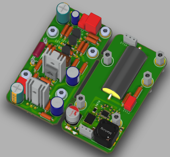
A big thank you to JPS64 for his superb layout design. As you can see, provision is made for a large film cap for the input coupler. The DCDC booster is SMT, but we sort can’t make these with TH parts anymore.
Attachments

Last edited:
It has much gain but I don't think that it can deliver this voltage. Thanks for the information.To get 40w into 8ohms requires 17.9Vrms or 51Vpp. Is the BA-3 preamp able to get you the output you need?
MOT disection
I have dissected one of my MOT's in the hopes of reducing the size/weight of the MOT, while still giving the proper Inductance and DCR values that work for the LuFo amp. I have removed both the primary and secondary windings, and I hope to rewind the EI transformer with the primary winding only, to provide the inductance and DCR required.
After searching transformer design and MOT design, I have chosen that my MOT is constructed from silicon steel w / high Bsat... Ur = 3000 and Bsat = 1.6T.
I have found a spread sheet, that simplifies the mathematical calculations, so it is quite easy to make changes.
One question before I begin to design the Inductor:
The core area is given by: CA=1.152 x sq.root (output V x output I)
Should the output voltage be Vp or Vp-p or Vrms?
The output I, will be 3 amps.
Thanks for the help, see pics below.
MM
Nice work, Myles! Very cool to get one gutted open. Want there a weld bead holding it all together? Did you grind through that? I see there is a plastic film for an air gap?
I would guess it is all Vrms based.
As long as you removed the thin secondary wire, is it possible to rewind a double strand of the primary wire to make a bifilar (dual balanced) inductor?
I would guess it is all Vrms based.
As long as you removed the thin secondary wire, is it possible to rewind a double strand of the primary wire to make a bifilar (dual balanced) inductor?
X, other interested parties,
Yes, there was a weld bead on each side. I used a thin cutting wheel attached to my angle grinder to remove the "I" section and mounting base of the MOT.
The thin plastic film you are viewing is actually a bad cut through the weld.
One could parallel 2 wires and make a bifilar wound primary. I have attached a pic of the primary winding. It shows the maximum amount of horizontally wound wire that can be put in the windows (14 turns of 18 awg wire I think). I was not going to venture into the SuSyLu area (yet😀). I would need to read up on bifilar windings.

If CA = sq.root of 39W x 1.152, this = 7.2 cm2 as a core area. I would like to increase the CA to 9.6 cm2 , as this makes a core of 3.2 cm x 3.0 cm, and I can decrease the stack height from 5.6 cm to 3.0 cm, saving some weight. This would only work if one can avoid core saturation and get the DCR and Inductance to measure properly also.
From my spreadsheet using the MOT as original size, one would only need about 5 turns of 18 awg wire to obtain 100mH, a DC resistance of the winding at 0.019 ohms, a maximum I of 15.5 A thru coil to keep flux below Bmax , and the energy stored in the coil is 12 Joule.
Since I am not a transformer / inductor designer, I am not sure how these values would actually work. The one parameter that may be to low to my eye would be the DCR. This and other values can be redesigned with different guage of wire and adjustment of other variables.
Please everyone, do not hesitate to give me advice on this adventure.
Thanks,
MM
Yes, there was a weld bead on each side. I used a thin cutting wheel attached to my angle grinder to remove the "I" section and mounting base of the MOT.
The thin plastic film you are viewing is actually a bad cut through the weld.
One could parallel 2 wires and make a bifilar wound primary. I have attached a pic of the primary winding. It shows the maximum amount of horizontally wound wire that can be put in the windows (14 turns of 18 awg wire I think). I was not going to venture into the SuSyLu area (yet😀). I would need to read up on bifilar windings.
If CA = sq.root of 39W x 1.152, this = 7.2 cm2 as a core area. I would like to increase the CA to 9.6 cm2 , as this makes a core of 3.2 cm x 3.0 cm, and I can decrease the stack height from 5.6 cm to 3.0 cm, saving some weight. This would only work if one can avoid core saturation and get the DCR and Inductance to measure properly also.
From my spreadsheet using the MOT as original size, one would only need about 5 turns of 18 awg wire to obtain 100mH, a DC resistance of the winding at 0.019 ohms, a maximum I of 15.5 A thru coil to keep flux below Bmax , and the energy stored in the coil is 12 Joule.
Since I am not a transformer / inductor designer, I am not sure how these values would actually work. The one parameter that may be to low to my eye would be the DCR. This and other values can be redesigned with different guage of wire and adjustment of other variables.
Please everyone, do not hesitate to give me advice on this adventure.
Thanks,
MM
From what I have seen, the primaries appear to be 14ga, and whatever windings they have there for North America 115vac mains the DCR is about 0.5ohms. If the primary pulls out nicely like that, one could make a corner out of block of wood and wind the wire externally. Then slip it on, then re-weld the plates. With a piece of shim stock to keep the air gap. The spreadsheet doesn’t sound right. There is probably 40-50 turns is my guess, and it is around 60mH and 0.5ohm.
Thanks X,
I re-installed the primary winding before beginning any of the previous posts, and measured with the "I" section removed, just to see what would happen. Readings were way low. I then put the "I" section on and put some pressure on it and the readings were more normal.
Not sure what is wrong with the spreadsheet, maybe operator error. Let me send the link to your etsy sight, and you can have a look.
I had to tap both of the windings off the tongue piece (tight fit). I guess if we are only worried about core saturation, induction and DCR, there is no need to have the primary winding spread across the window horizontally and short vertically. I would rather wind it vertically along the tongue(core), to the correct number of turns. I am going to check some of the formula's used in the spreadsheet, and compare them to other's on websites dealing with transformer/coil design.
Only beginning,
MM
I have been waiting to receive my LUs (thanks Will), now I have ordered the boards.
I have real anticipation now 🙂
I have real anticipation now 🙂
Hi Myles,
If you ever feel adventurous enough to get maybe 100ft of 14ga wire and double it up for bifilar wind and wrap as many turns as can fit into the same space using a rectangular former that matches the core, I would be interested to see if a home made (DIY) balanced bifilar choke can be made effectively. Once the secondaries are removed, the space would double. So my guess is it would exactly two circa 60mH x 0.5DCR chokes would result. The winding is tough going though as 14ga is thick stuff. If you have a powerful lathe that runs at low speed it might make the winding very easy.
If you ever feel adventurous enough to get maybe 100ft of 14ga wire and double it up for bifilar wind and wrap as many turns as can fit into the same space using a rectangular former that matches the core, I would be interested to see if a home made (DIY) balanced bifilar choke can be made effectively. Once the secondaries are removed, the space would double. So my guess is it would exactly two circa 60mH x 0.5DCR chokes would result. The winding is tough going though as 14ga is thick stuff. If you have a powerful lathe that runs at low speed it might make the winding very easy.
Hi X,
I may do that, but first I am trying to get my head around some electromagnetic concepts and equations. Maybe you could help me out.
Is the voltage that the MOT sees, the 1.55 V across the source of J1, and is the A that the MOT sees the 3 A that is bias V. I am asking this as I am trying to reduce the size and amount of windings, but still want the design to work.
I guess I am asking if you know the max V and I that one should design the inductor to handle?
Thanks for the help,
MM
I would design for DC of at least 5A and a DCR of about 0.5ohm. The rest will be whatever you can get. If you were making an inductor from scratch it would be good to predict what the windings and core size will be etc.
Tpically, you can design the around how much power do you think a block of iron and copper windings can take? I would hate to put more than 20w or so into it.
Use Ohms law for power dissipation: P = V^2 / R or V=sqrt(P R) = sqrt( 20W x 0.5ohm) = 3.16V max voltage drop across the MOT.
Tpically, you can design the around how much power do you think a block of iron and copper windings can take? I would hate to put more than 20w or so into it.
Use Ohms law for power dissipation: P = V^2 / R or V=sqrt(P R) = sqrt( 20W x 0.5ohm) = 3.16V max voltage drop across the MOT.
Thanks X,
Will let you know what i come up with. As a start the theoretical effective core area is 1.152x sqrt (V x I), so if using I=5 and V=4, the core area is 5.15 cm2 or 515 mm2. I think this will be a little small for what I need, but will see how it works and then modify as necessary.
MM
Will let you know what i come up with. As a start the theoretical effective core area is 1.152x sqrt (V x I), so if using I=5 and V=4, the core area is 5.15 cm2 or 515 mm2. I think this will be a little small for what I need, but will see how it works and then modify as necessary.
MM
Today I got the 5 pcbs from JLC ,And I only need 1 of them (one spare).
I thought I give away 3 of them.( You pay only for shipping).
This is revisison 1 of the board.
If you want one send me a P.M

I thought I give away 3 of them.( You pay only for shipping).
This is revisison 1 of the board.
If you want one send me a P.M
- Home
- Amplifiers
- Pass Labs
- LuFo Amp - 39w SE Class A from 28v Rail