Thanks, I appreciate all the "likes" and comments.
Before I started out, I thought that KiCad and the process of creating pcbs daunting. But taking one step at a time, it became a very manageable learning process. Whenever I got stuck, I searched the internet for solutions. I think my previous experience with LTSpice and manually laying out my perf board circuits helped me to get up to speed with KiCad, although at a very slow speed.
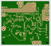
I have done a bit more tweaking of the board. So now to mirror the board for the other channel. I have not found a way to effectively do that with KiCad so I am manually deleting the copper traces and manually repositioning all of the footprints and redrawing the traces. At least KiCad allowed me to mirror the image of the board so I can use the image to help me relocate the footprints to the mirrored locations.
Then the big question is whether the boards will work in real life. Once the designs are done, I'll have to order some boards and test them.
Before I started out, I thought that KiCad and the process of creating pcbs daunting. But taking one step at a time, it became a very manageable learning process. Whenever I got stuck, I searched the internet for solutions. I think my previous experience with LTSpice and manually laying out my perf board circuits helped me to get up to speed with KiCad, although at a very slow speed.
I have done a bit more tweaking of the board. So now to mirror the board for the other channel. I have not found a way to effectively do that with KiCad so I am manually deleting the copper traces and manually repositioning all of the footprints and redrawing the traces. At least KiCad allowed me to mirror the image of the board so I can use the image to help me relocate the footprints to the mirrored locations.
Then the big question is whether the boards will work in real life. Once the designs are done, I'll have to order some boards and test them.
super symmetry what elseme likee (did't check anything)
why mirroring other channel?


You’ll find it supremely addictiveThanks, I appreciate all the "likes" and comments.
Before I started out, I thought that KiCad and the process of creating pcbs daunting. But taking one step at a time, it became a very manageable learning process. Whenever I got stuck, I searched the internet for solutions. I think my previous experience with LTSpice and manually laying out my perf board circuits helped me to get up to speed with KiCad, although at a very slow speed.
I have done a bit more tweaking of the board. So now to mirror the board for the other channel. I have not found a way to effectively do that with KiCad so I am manually deleting the copper traces and manually repositioning all of the footprints and redrawing the traces. At least KiCad allowed me to mirror the image of the board so I can use the image to help me relocate the footprints to the mirrored locations.
Then the big question is whether the boards will work in real life. Once the designs are done, I'll have to order some boards and test them.


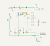
Whoops, I found a mistake. The mirrored optocoupler to avoid crossing wires in the LTSpice schematic messed up my brain. Here is the corrected KiCad schematic. I have made the correction but now I am contemplating some re-arrangement of footprints and re-routing of traces to tweak it some more. The joys of diy.
Attachments
Last edited:

My mono-blocks are mirrored so I want left and right channel boards. If I could mirror the footprints on the board, I would only need to re-route where needed.
Also more diy, more fun!
I personaly, being a cheapskate, avoid mirroring. Jlcpcb provide a minimum of 5 boards per design, so single, identical channels make a bit more sense
I was having Kosher approach years ago, thinking "everything must be identical between channels" ........ then - that's another thing I learned from Pa - if he's completely happy having L vs. R channel pcbs sort of mirrored for his FW products, then ........
but, frankly, if I can avoid it ..... if nothing else - less work in Eagle that way
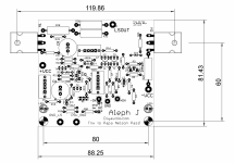
completely dependable of OS part arrangement; when you have one row of TO247 parts, reasoning is to put them on lower 1/3 of heatsink height and we like to have input on one end of pcb ..... mirroring is a must
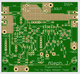
other example is - say - Babelfish Aleph J - pcb small enough that input is sorta centered physically - so no need and no benefits of mirroring
here is, as illustration, probable Store B J
just imagine it upside-down on hsnk
but, frankly, if I can avoid it ..... if nothing else - less work in Eagle that way
completely dependable of OS part arrangement; when you have one row of TO247 parts, reasoning is to put them on lower 1/3 of heatsink height and we like to have input on one end of pcb ..... mirroring is a must
other example is - say - Babelfish Aleph J - pcb small enough that input is sorta centered physically - so no need and no benefits of mirroring
here is, as illustration, probable Store B J
just imagine it upside-down on hsnk
Attachments
TRUE STORYbeen there, done that
in every program, you can rotate and flip symbols, to keep it more logical/understandable

- Home
- Amplifiers
- Pass Labs
- Single Ended Tokin SIT THF-51S Common Drain Mu Follower Amplifier, 45W?