It's really hard to tell, but it almost looks like you're connecting the red cable (speaker positive) to -o?
I put a red wire from G on amp PCB and the black from O-. So G goes to red (+) speaker post.
brave man ; )
I´m really curious for your listening impressions between M2x and Vfet. Can u give me a link to your monoblocks? would like to see build and what you wrote about sound
tnx and best,
st
My M2X posts are all over the M2X thread as I have tried different input boards and also made modifications to PSU to get as low noise as possible. Think I succeeded. It is a very nice amp so VFET will have a hard time to compete I think.....but time will show. Never tried the Ishikawa board on M2X but VFET FE board looks a bit similar even that Edcor is coupled as a normal transformer and not as an "auto" in M2X.
Attachments
SMPS with a good filter will save a lot of time/money for future builds if this becomes the "standard"......
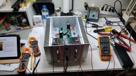
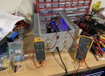
Number 40 is up and running on the test bench. 20 volts at the test point and holding steady. Will pass a sine wave. Measured approximately 1.2 volts across R1, R2.
Can see your back panel also bends inwards a bit. On the larger chassis a shim behind the 4 screws (between panel and heatsink) cured it. But don't know if I will disassemble to make this modification. Forgot it to do it from start....
Interesting that the front panel gets as hot as the heatsinks even that there are no paste between heatsink and front panel.
Mine has a little bend as well but barely noticeable. Less than that. Not sure what shims can do though since the panel itself is bent.
M2x vs the VFET.
The two cannot be compared straight up. At this point I wouldn't know which one to give up. I may know at some point but not yet, they are different and the cedarburg is not ready yet. Based on the rumors, I may need a cedarburg for the VFET as well. The VFET is tube like and makes you want to be physically closer to the speakers, it brings out the best in old poorly recorded material. I think tube ampification explains how the old material was recorded and judged to be good enough for distribution. With new material the comparison becomes more subtle. Clearly there is a difference in power and punch maybe but not as much as I thought.
The two cannot be compared straight up. At this point I wouldn't know which one to give up. I may know at some point but not yet, they are different and the cedarburg is not ready yet. Based on the rumors, I may need a cedarburg for the VFET as well. The VFET is tube like and makes you want to be physically closer to the speakers, it brings out the best in old poorly recorded material. I think tube ampification explains how the old material was recorded and judged to be good enough for distribution. With new material the comparison becomes more subtle. Clearly there is a difference in power and punch maybe but not as much as I thought.
Mine has a little bend as well but barely noticeable. Less than that. Not sure what shims can do though since the panel itself is bent.
I think the back panel is bent a bit by the force when attached. The heatsinks is just a tiny bit longer when the rail is "centered". Then a shim between rail and back panel can fix it. Maybe if rail is adjusted a bit to the rear so back panel just clears the heatsink this will probably fix it also.
The fix worked for the large DeLuxe chassis and was recommended by "Dirk" as far as I remember 🙂
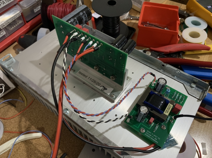
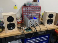
VFET number 010 is now singing! Everything went very smoothly. I used silicone RC race car/quad copter wire (18ga, 16ga, and 28ga). Also used crimped pin connections to solder into boards. 18ga for doubled wires from PSU jack to filter board. 16ga double wire (black and red) from CLC filter to amp and same 16ga silicone wire from amp to speaker outputs. All signal wire is 28ga silicone insulation as well. It turned on around 16v at VFET source pin. Adjustment was easy and stable. Bias current was measured at 1.7A and very stable. I am using my own design balanced/SE buffer with gain set at 14dB for now. I think it could probably use the 20dB setting for overall 30dB which should let my phone as source hit clip levels. Listening to the VFET on my Rockville speakers (LS3/5A homage with about 8-12ohm nominal impedance). The amp sounds wonderful.
Thank you to Mr Pass and the DIYA team that made this amp possible!
Connections to boards:
Adjusting voltage of S pin for VFET to 20v:
https://www.diyaudio.com/forums/attachment.php?attachmentid=948319&stc=1&d=1620027819
Playing music through iPhone (Amazon HD) to buffer as preamp (14dB) and Rockville speakers:
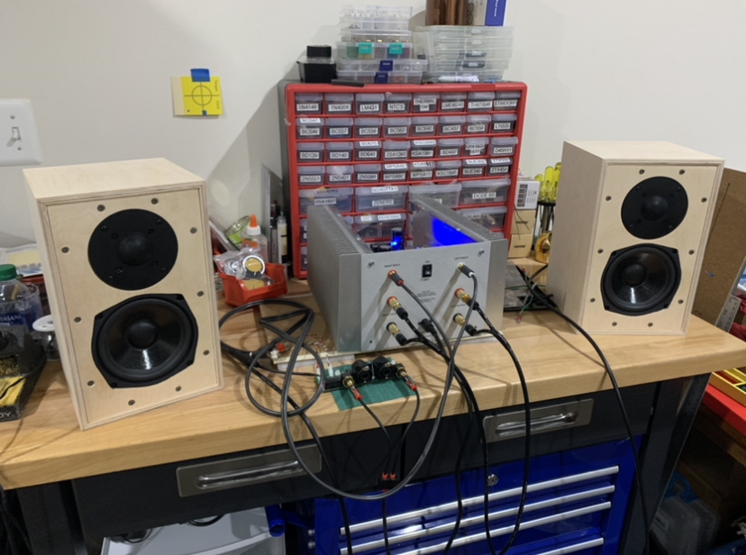
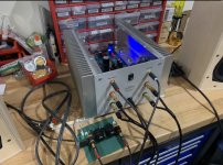
Closer shot with preamp:

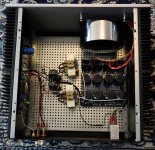
Closer ahot of the inside. I will let let it burn in without the chassis fully built for a few days before buttoning it up with all panels.
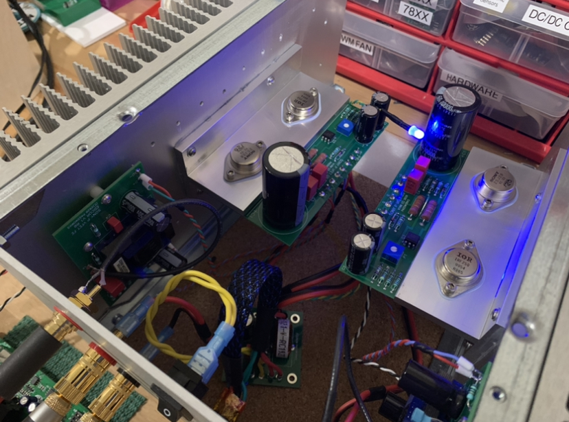
Temperature of the thermal spreader is 51C (IR thermometer with Kapton tape surface).
Thank you to Mr Pass and the DIYA team that made this amp possible!
Connections to boards:
Adjusting voltage of S pin for VFET to 20v:
https://www.diyaudio.com/forums/attachment.php?attachmentid=948319&stc=1&d=1620027819
Playing music through iPhone (Amazon HD) to buffer as preamp (14dB) and Rockville speakers:
Closer shot with preamp:
Closer ahot of the inside. I will let let it burn in without the chassis fully built for a few days before buttoning it up with all panels.
Temperature of the thermal spreader is 51C (IR thermometer with Kapton tape surface).
Attachments
-
 50D9FE0A-CB6D-4ABB-A7B0-F515850CB44A.jpeg484.4 KB · Views: 790
 -
 4B3BBDAC-A368-4C34-A7DD-9DA58FE4A1AD.jpeg521.2 KB · Views: 174
 -
 1BBC54C4-CE37-4CB6-9BB9-0ABB99A874FB.jpeg434.8 KB · Views: 1,005
 -
 175ED1B6-2A0A-4C28-B327-0AAE52C34A88.jpeg522.9 KB · Views: 549
 -
 F8DBAC5A-635E-4EFC-AB45-F8B1D8AEC4C1.jpeg518.8 KB · Views: 811
Last edited:
yes
if it's a problem in your configuration you will have no choice but add a speaker protection, either from the store or a chinese (or not) chip based variant.
if it's a problem in your configuration you will have no choice but add a speaker protection, either from the store or a chinese (or not) chip based variant.
Last edited:
I recall that the M2 would take about 45 seconds to slowly charge up to reach its steady state bias current and did not have a turn on or off thump issue. I was expecting the VFET to behave similarly but the turn on was almost instantaneous as I monitored bias current. I think it’s the RC time constant of R5+R7 and C2. It’s about 4s for the VFET vs about 115s for M2. I wonder if Mr Pass or ZM could suggest a longer setting here or are there other considerations at play? Making C2 3300uF would slow down the thump by 3x.
how big is that thump, speaking in mm movement of bass cone ?
approx 5mm on a 8" Fullrange (Visaton BG20). Does not seem alarming at least in my set..
best
st.
I've built a VFET compatible drop-in card using a PNP bipolar (MJL1302A) as the follower, instead of a Pchannel VFET. Rev.A of this board did include an output muting relay with 16 ampere contacts. But, alas, the board did not fit comfortably with all the other things on the heatsink and inside the chassis. There were collisions. So I was forced to shrink the board footprint, and unfortunately the muting relay and the clipping indicator got tossed overboard. Jettisoned. 86'ed. Flung into the latrine.
Anyone who's considering adding a pair of muting relays: I wish you good luck, and I hope you succeed where I have failed.
Anyone who's considering adding a pair of muting relays: I wish you good luck, and I hope you succeed where I have failed.
Hi Mark,
One could always use a very compact SSR between the output cap and speaker binding posts. It could use a circa 60A low RDson MOSFETs that can have a delayed turn on and instant turn off to prevent thump via some simple control circuitry. But I was hoping for a simple solution by modifying the value of the RC in front of the optoisolator a la M2.
Can you share with us what the drop-in VFET replacement card looks like? Is it now running?
Thanks,
X
Last edited:
Hi Mark,
Which “that” are you referring to nobody gonna design? The SSR, the new RC constant, or the VFET BJT drop in (which I thought you said you made)?
Which “that” are you referring to nobody gonna design? The SSR, the new RC constant, or the VFET BJT drop in (which I thought you said you made)?
Can you share with us what the drop-in VFET replacement card looks like? Is it now running?
(1) No; (2) No; It's an experiment and experiments sometimes fail. Rev.A failed, for example. Don't hold your breath, it may never appear.
Hi Mark,
Except that option (1) has already been designed and tested for other amps. I can only speak of it in generalities though...
Except that option (1) has already been designed and tested for other amps. I can only speak of it in generalities though...
- Home
- Amplifiers
- Pass Labs
- DIY Sony VFET Builders thread