Hi,
I saw many PS boards without safety earth connected .... or I'm wrong and it is not needed?
Read post#778 and take your pick.
When I measure MW Safte Earth in it goes to "V-" and the shield, that's why I asked.
[EDIT]
@oreo382,
thanks. I must have read over that.
[EDIT]
@oreo382,
thanks. I must have read over that.
Last edited:
 Have a nice Sunday
There have been reports that safety earth is not connected via the Meanwell power connector but I have not checked myself.
The redundancy of grounding covers supplies with or without the earth/chassis ground.
The samples of this supply have the earth ground attached to -V
Aleph J?
that rise interesting question .........
is it possible that Aleph J is going back in production of FW ....... or that is directly for Greedy Boyz (Store) ?
1600 Biguns is plenty of channels ......... be it 2 or 4/channel

It is for the store. I expect to ship them next week.

The redundancy of grounding covers supplies with or without the earth/chassis ground.
The samples of this supply have the earth ground attached to -V
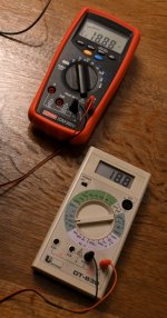
yes i have mesured 10R between chassis and Speaker OUT + ( the Thermistore resistance ) 🙂
Safe enough for me and a Way safer than my other amps 😀
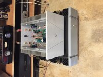
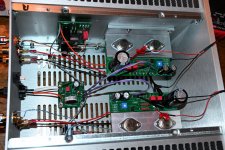
Number 77 up and running...
Straightforward build, no major issues and right away measured 20.2 volts at both channels! At first try left channel input lead had broken off at the board connection. Fixed that and sounding beautifully. Will give another testimony when broken in. Has a lot of worthwhile competition .... FW F4 and Pass XA-25....
Straightforward build, no major issues and right away measured 20.2 volts at both channels! At first try left channel input lead had broken off at the board connection. Fixed that and sounding beautifully. Will give another testimony when broken in. Has a lot of worthwhile competition .... FW F4 and Pass XA-25....
Attachments
Not sure if anyone saw my question from earlier post - are the Toshiba's also matched Quads?
My kit has the Toshiba 2SK370GR and 2SJ108GR and not the LSK170/LSJ74’s. Can I assume that the Toshiba’a are also matched quads?
Ok, thanks. I missed that as the discussion a few pages ago showed LSK/LSJ parts. Great to know and a big thank you to Mr Pass for doing the matching himself! 
Seems my amp is up and running. At least it can output a 1kHz sinus in 8 ohm dummy loads. The DC-voltage at the test point needs a fine tuning. It stays about 18.8 - 18.9 VDC. Not much change from cold to warm.
Good it works as it would be a bit time consuming to debug it for errors.....unsolder wires etc.....
Next step after adjustment would be to listen to the amp. I am using my M2X mono blocks in the moment and have just put in the Cedarburg input boards. The M2X amps are quite heavy to move.....but I will test the VFET amp in the near future with real music instead of a 1kHz test tone.
Attachments
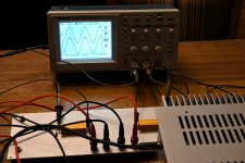
It's really hard to tell, but it almost looks like you're connecting the red cable (speaker positive) to -o?
.....but I will test the VFET amp in the near future with real music instead of a 1kHz test tone.
brave man ; )
I´m really curious for your listening impressions between M2x and Vfet. Can u give me a link to your monoblocks? would like to see build and what you wrote about sound
tnx and best,
st
Speaker+ is circuit Ground.
Yes , but I referred to MEPERs pictures
Because that's where it goes. Beaten to it.
No, speaker positive goes to ground. Like Ben Mah posted
That depends where he inverted it, I took a black wire from ground to the positive output, to make clear it's inverted, but you might as well put a red wire from ground to positive output... not sure if that was your question
I didn't have any question about how to connect it. I asked MEPER about his. You can of course connect however you want, and you could even the speakers red to black and black to red outside of the amp too. But you are bound to forget to do so and anyone else wouldn't know.
My intention was to make him sure that was what he wanted.
My intention was to make him sure that was what he wanted.
- Home
- Amplifiers
- Pass Labs
- DIY Sony VFET Builders thread