Well, you know I will! Much to my fear of losing your patience.
I have moved it from various outputs of the DSP.
The buzz WAS still there when I fed it with the HF signal of the same channel.
I will try it all over again.
To my audio confessor: I did the best wiring yet on the last amp but did not notice until I had turned it on a few times - to the sizzle of the the fuse blowing after about two seconds - that instead of putting the 2 x 9 volts secondaries in series I had shorted one of them and had connected only one secondary to the bias circuit. I have no idea what it was being fed.
The first two times it would light the LEDS - the last time they did not light. DAMNIT.
I figured I destroyed the transformer - I do no trust it - so i had a smaller 8 + 8 transformer inserted that in, having used it recently I know it works - but no LEDs.
My guess is I destroyed the IRF 510.
I am going to verify the power supply is working properly - feel sure the higher voltage one is since when the LEDs would light I would see the expected voltage there. But with all power leads disconnected I am going to verify the 16 volts transformer is working. I am sure it has to be but while at it ...
If you see this in the next hour or so - it seems to me no harm could be done with power connected ONLY to the bias supply. I figure checking the voltage after the input cap would verify it works. Is there a voltage I should see there?
Another question: Is it safe to have the power connected to the big MOSFET but no power connected to the bias supply? Would the LEDs light in this situation?
Now to get to work.
THANKS, ZM
just biasing PSU active, OK
just big PSU - bummer
can't say what is going south, but hope no big ones ..... as I hope you had temporary fuse inserted in +60, as I advised
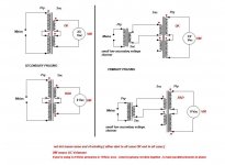
LEDs should lit in case that you have just big PSU active, but there will not be current through input JFets, so gate of SIT is float ....... most likely conducting ...... taking what Mu above can give ..........
in any case - use your diode tester to check LEDs, try poking IRF510 too....... if you have spare one, just replace it .......... even if I think it survived - there wasn't substantial current
anyway - whatever you have spare, replace if in doubt
you can put there 510,520,530, 610,620,630 .......... no functional difference - that's just voltage umbrella for JFets
just big PSU - bummer
can't say what is going south, but hope no big ones ..... as I hope you had temporary fuse inserted in +60, as I advised
LEDs should lit in case that you have just big PSU active, but there will not be current through input JFets, so gate of SIT is float ....... most likely conducting ...... taking what Mu above can give ..........
in any case - use your diode tester to check LEDs, try poking IRF510 too....... if you have spare one, just replace it .......... even if I think it survived - there wasn't substantial current
anyway - whatever you have spare, replace if in doubt
you can put there 510,520,530, 610,620,630 .......... no functional difference - that's just voltage umbrella for JFets
Main power supply is fine - not connected to anything.
Even the second 16 volts transformer is the problem. Resistance of each side seems to make sense.
Very strange. I need to figure what the hell I have done with this simple aspect.
Will make sure bias is working by itself before going any further.
THANKS, ZM
Even the second 16 volts transformer is the problem. Resistance of each side seems to make sense.
Very strange. I need to figure what the hell I have done with this simple aspect.
Will make sure bias is working by itself before going any further.
THANKS, ZM
If I did not know how to wire them correctly i would not know I had wired it wrong!
Ended up using, temporarily, one half of a 15 volts 300 VA transformer and that works fine.
My mains AC from the isolation transformer is 127 volts. The other one is just under 1:1 - about one volt lower than actual mains - 124 volts. That is rather high but to go to the 110 taps would be too low. The other amp using the same isolation transformer is fine - only difference is the 25 plus 25 400VA transformer is used there. I just remembered I have a 24 plus 24 300VA - would you recommends substituting that?
What was weird was I had used the 16 volts - EI SIGNAL to power the fans on the left side until I realized (at nine volts) it was makign the fans spin too fast - of course followed by a bridge and capacitors.
Ran out of time.
Saw the LEDs working and was able to set the P1 to 20 mA.
TODAY
i attached one of your pins to a fuse holder and solder the existing pin of the purple wire to the other side. I had a fuse holer wihich had a hole in the tab and was able to enlarge this to fit the pin and soldered it in. I have noticed the pins are easy to clean off the solder and the holes in the pcb large enough for some wiggle room.
I made sure all pots were at maximum value.
Turned it on and there is 340 mV across the resistors. But 60+ volts across the SIT. I do not remember this value being anywhere near that high at first turn on but I made no notes.
Before I could make any adjustments the fuse in the purple wire blew. 2.5A sloblo. It was on a minute or so.
What do you think I should do next?
I should remember but I do not from the previous three - but does turning P2 clockwise lower the the Vgs? I know ti affects both values - one goes lower while the other goes higher but I do not want to raise the Vgs any further so I will wait for your advice.
THANKS, ZM
I have verified that SIT P2 and P1 Mu board trimmers are at max value.
There is 12 volts on the output of LM317 - measured between R9 and 317 output.
I was worried the bias supply was not working and that explained the high Vgs.
For what it is worth pras assigned a Vgs of 2,41 V.
There is 12 volts on the output of LM317 - measured between R9 and 317 output.
I was worried the bias supply was not working and that explained the high Vgs.
For what it is worth pras assigned a Vgs of 2,41 V.
Last edited:
in this moment, without pcbs close to me and trimpot and DMM...... I can't tell anything about trimpots and CCW or CW
spending zilliarda of years in repair business, abandoned expecting logic in CCW/CW for trimpots, so not even bothering to take care about the same when making my own pcbs
simple - trust in what your DMM is telling you, not someone else's convention
so - post #29 here:
big Donuts - 300VA is sorta OK-ish, you can use that one on speaker channel (mids, tweets) asking for less juice, if resulting DC is (in the end) close to prescribed 60Vdc
rail, in general - better to have 65Vdc than 58Vdc
spending zilliarda of years in repair business, abandoned expecting logic in CCW/CW for trimpots, so not even bothering to take care about the same when making my own pcbs
simple - trust in what your DMM is telling you, not someone else's convention
so - post #29 here:
-just for fun, check what voltage you can set twiddling with P2 - you can use SIT Gate pad for red probe ; so , you confirmed that twiddling with P2 is giving a change, now set it to max neg voltage and be done
big Donuts - 300VA is sorta OK-ish, you can use that one on speaker channel (mids, tweets) asking for less juice, if resulting DC is (in the end) close to prescribed 60Vdc
rail, in general - better to have 65Vdc than 58Vdc
Last edited:
I verified pots were set to maximum using the DMM - so I am sure they are where they are supposed to be for first turn on with the purple wire attached.
So I tried it again - on turn on I get 336mV across the resistors and 68 volts Vgs - when I lower the Vgs the voltage across the resistors goes higher but I can only get down to about 60 volts with P2 and 460 mV across the resistors.
These are the boards I used on the first amplifier so I know they worked. The SIT is from the second paid I got - the other one is in the amplifier below which is working just fine.
So there is no way to adjust this SIT to where it needs to be with the boards as configured.
The only way I can think of to lower the Vgs is lower the B+ which is more like 75 volts.
Thinking about your comments about getting your power transformer made to your specification and the main thing I remember about that you asked for a larger core. With that in mind I wonder if the clever trick would be to get a twice as large VA transformer and only use half of it?
This occurred to me when I substituted the 300VA `15 transformer (which delivers 17 volts to the rectifier. This is temporary - I doubt a huge core makes a difference here.
The price for such from ANTEK is an extra twenty dollars or so.
The amplifier finished previously using the same AC power as the one I am working with now, using a 25 + 25 volts transformer I was able to get 36 volts Vgs without any problem at all. This amp is using the other half of the pair I got from pras.
My rail is 10 volts higher than 65 volts.
I guess it is a good thing you told me to put that fuse in the line! DId not do it before. Got lucky
By the way if anyone wants to know - all of the triimpots are at the prescribed value when turned fully counterclockwise. That is what i had remembered but I did make sure it is true.clockwise.
Last edited:
Rick
measure this:
- DC voltage at SIT gate ( red probe to SIT gate, black probe to GND) with P2 fully CCW , also measure SIT Uds in same moment, write here
- DC voltage at SIT gate ( red probe to SIT gate, black probe to GND) with P2 fully CW , also measure SIT Uds in same moment, write here
measure this:
- DC voltage at SIT gate ( red probe to SIT gate, black probe to GND) with P2 fully CCW , also measure SIT Uds in same moment, write here
- DC voltage at SIT gate ( red probe to SIT gate, black probe to GND) with P2 fully CW , also measure SIT Uds in same moment, write here
I have already made my confession to ZM - but to anyone else who has read this if you have a SINGING BUSH with excessive voltage across the SIT - first thing to check is if you have the MOSFET right side up.
Hope I did not blow it up - will know this evening.
Mis-wired power transformer and improperly installed MOSFET - not just anyone could do that.
Hope I did not blow it up - will know this evening.
Mis-wired power transformer and improperly installed MOSFET - not just anyone could do that.
It can happen. I miswired a THF-51S and it survived. I reversed the drain and source wiring in a follower output and it produced music. I even checked the 1W THD and it looked good. So I listened to it for a couple of days.
I finally realized something was wrong when I went to measure the distortion at higher power levels and found huge amounts of distortion. I was puzzled, but after close methodical inspection of the wiring I found the reversed wiring. I had applied negative Vds to the THF-51S, it provided good music at low power, and I was happily enjoying it. If I hadn't tried measuring distortion at high power output, I might not have realized my wiring mistake.
I finally realized something was wrong when I went to measure the distortion at higher power levels and found huge amounts of distortion. I was puzzled, but after close methodical inspection of the wiring I found the reversed wiring. I had applied negative Vds to the THF-51S, it provided good music at low power, and I was happily enjoying it. If I hadn't tried measuring distortion at high power output, I might not have realized my wiring mistake.
Ben Mah,
Thanks for the story. I do not feel QUITE so stupid if even someone like you can do this!
But I bet you never mis-wired a transformer.
Luckily, the amp survived my insults.
Both of the devices are obviously rugged and insults do not faze them. We should all be like them.
Thanks,
Thanks for the story. I do not feel QUITE so stupid if even someone like you can do this!
But I bet you never mis-wired a transformer.
Luckily, the amp survived my insults.
Both of the devices are obviously rugged and insults do not faze them. We should all be like them.
Thanks,
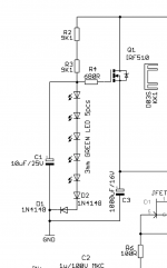
(1V93*5+0V65*2)-4V, then first higher standard
10V95-4V=6V95, so 16V
hard to find 10V
or isn't?
Thanks! Was just sourcing caps for the next SB and was struggling to find adequate selection for this one.
") , is there an Idss you'd recommend?
, is there an Idss you'd recommend?2up, 2down
prescribed Iq 20mA, divided by 2, so each getting 10mA
strong BL would do
latest Papa's Lecture sez that, say, 8mA Idss is OK
Beyond the J Fringe
I prefer that you bias them to sum 20mA than that you bias them to Idss if it's lower
didn't I read what Pa said, I would advise latter
prescribed Iq 20mA, divided by 2, so each getting 10mA
strong BL would do
latest Papa's Lecture sez that, say, 8mA Idss is OK
Beyond the J Fringe
I prefer that you bias them to sum 20mA than that you bias them to Idss if it's lower
didn't I read what Pa said, I would advise latter
Last edited:

- Home
- Amplifiers
- Pass Labs
- The Singing Bush Tips 'n' Tricks