Excellent constructionFinally, I finished Singing Bush
.......................

Finished making the buzzer's wiring the same as the others whcih entailed taking the whole thing apart, almost.
Was hoping there was something wrong in the wiring but there is no change.
Measured Vds and Vgs for both -= the buzzer 36.6 volts - 3.707 volts
For the one in question - 34.37 volts and 3.66 volts.
I await your instructions.
THANKS
Was hoping there was something wrong in the wiring but there is no change.
Measured Vds and Vgs for both -= the buzzer 36.6 volts - 3.707 volts
For the one in question - 34.37 volts and 3.66 volts.
I await your instructions.
THANKS
increase R11 (SIT pcb) to 4K7 and I believe that Ugs will go down enough
regarding Buzzer - you said that you changed practically everything except SIT itself
hoping that you'll get replacement SIT soon, and that buzz will be gone after replacement
even if I really can't explain what could be wrong with SIT ......... but, that's way above my pay grade
regarding Buzzer - you said that you changed practically everything except SIT itself
hoping that you'll get replacement SIT soon, and that buzz will be gone after replacement
even if I really can't explain what could be wrong with SIT ......... but, that's way above my pay grade
Regarding the buzzer - everything at least once.
The PCBs originally installed in buzzer are now in amp #4 and not a noise to be heard - well if you stuff your head in the horn you can hear the noises you would expect to hear.
The replacement SIT is on the way - two weeks ago. Maybe another two weeks until it is received.
Now if it STILL buzzes after that ...
Now to go find a 4.7K resistor.
BUT WAIT a question - I am using the both sides series connection for the power transformers on amps #1 (buzzer) and #2.
I had mentioned that both of these transformers run hotter than` the paralled primary ones in amps 3 and 4. Is this to be expected. Not anywhere close to hot but noticeable warmer than the usual arrangement.
Of course, I think the left channel, which uses the all series transformers sounds more lively. As I continue to believe - nothing wrong with a placebo as long as you can continue to believe it.
THANKS, ZM
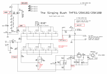
please, refresh my memory with all details about xformers "both sides series connection"
and, even if my cognitive mechanismus is primary visually oriented, I'll try to grasp whatever you write (counting on fact that you are definitely challenged in bringing visual material )
)
and, even if my cognitive mechanismus is primary visually oriented, I'll try to grasp whatever you write (counting on fact that you are definitely challenged in bringing visual material
)Both sides of the power transformer wired in series. The primary is in series and the 50 volts secondaries are in series.
Found a 4k7 resistor and installed it.
I assume all else was to be left the same so that is what I did.
Vgs is almost doubled to just over 7.
Vds is impossible to lower to less than 65 and !q reading is around 150 Ohms,
Bias pot and mosfet pots are both fully clockwise
I did not leave it on long.
What should I try next?
I take pictures and then forget to do anything with them when I get to work.
Both sides of the power transformer wired in series. The primary is in series and the 50 volts secondaries are in series.
in that case - try "normal" connection of both primaries in parallel and both secondaries in parallel , and investigate in which arrangement Donut is colder
Found a 4k7 resistor and installed it.
I assume all else was to be left the same so that is what I did.
well, it is pretty irrelevant are you going to do it before changing value of 1K5 or after, but turning trimpot opposite of previous situation is logical thing - simply observing Iq and SIT Uds
Vds is impossible to lower to less than 65 and !q reading is around 150 Ohms,
Bias pot and mosfet pots are both fully clockwise
if you're sure that you tried entire range of Ugs (so moving trimpot full scale) you have now at disposal, that means that increase of 1K5 is too much, so go back and increase it in smaller amount
if you did mount 4K7 there, go with 2K2
reason for entire trouble is .... well, most likely that SIT having borderline Ugs value
and - as always - I don't care about CW and CCW info - that's just another possible detail leading to misunderstandings - I believe in what I see on DMM, not in my memory or anybody else's
The numbers I reported were with the 4K7 as R11 - no R10 and R12 bypassed with 10K.
When I see the number falling with reversing of the pot I assume that is the way it will continue.
Are you saying there could be a fall in both Vds voltage and the Iq number and then it could increase again with pot position?
i installed a 2k resistor and Vds is 29 volts - Iq can be set to 460 mV.
B+ is just under 66 volts so something is dropping lots of voltage.
With 1K5 I could get 34 volts..
Having no knowledge of how the circuit works simple logic would lead one to believe I need to make R11 smaller in value.
I will move both pots back to starting position - which is fully counterclockwise - I do not understand why you do not care about that but I figure in time I will.
I will worry about the transformers later - if they were getting hot I would do something just warmer than the other two. From what I think I remember this probably due to all fo that extra copper in series.
As you feared I will keep you posted!
THANKS, ZM
set trimpot on SIT pcb to get closest to 35-36V at output node (or sit drain, whatever easier to put clip on)
then fiddle with trimpot at MOS pcb, to get as close to desired Iq
it is iterative process, Iq being pretty stable when you're in broader area of desired Uds of SIT
CW and CCW - I don't care for orientation of trimpots when designing circuit and pcb, thus I can't give exact directions in form "rotate it CW to get more......"
edit - if you can't make lower Ugs for SIT increasing R11, then go the other way - put 1K5 back, add another 10K across R12
don't forget to fiddle with trimpot at SIT pcb afterwards
if you already set Iq with trimpot at MOS ocb, there is no need to fiddle with it more
Last edited:
ZM - I have set three of these working as you specified so I know how to do the iterative process.
With the other three I found Vds very high at start up and turning the trimpot clockwise lowered the voltage. With the mosfet pot I turned it clockwise to raise the Iq. I found both have the opposite effect for the other voltage. Which is the basis of the iterative process.
Set both pots back to start position and moved from there.
I find the pot for bias is not making much of a difference at all from start to finish.
I measure Vgs and it is 30 volts - so that is where the Vds is going.
This scared me to death so I connected a speaker and it still works - I thought I had blown the thing. I did not leave it on for more than five seconds to verify music would come out of it.
This is with the 2K resistor in effect which seems rather strange compared to what happened with the 1.5K.
I would be glad to try higher value resistors but that seems futile to me since the higher the value ti only makes things worse.
Should I try 1.3K for R11?
Sorry to be such a bother.
What value of Vgs is desired?
THANKS,
I don't know what you're doing but logic is simple
mosfet is already set to push as much juice we want
now, intrinsic resistance of SIT itself is defining what voltage will show across its power pins (D,S)
higher resistance, more volts, higher output node voltage level
we are setting intrinsic resistance of SIT varying its Ugs voltage
smaller Ugs in absolute value**, SIT more open - lower intrinsic resistance - lower Uds voltage - lower output node voltage level
higher Ugs in absolute value**, SIT less open - higher intrinsic resistance - higher Uds voltage - higher output node voltage level
**always negative, gate must be lower in DC level than Source
now, increasing value of R11 (SIT pcb) will push entire trimpot down, in voltage domain
again, decreasing value of R11 (SIT pcb) will push entire trimpot down, in voltage domain
varying up to 50% of value , one or both of these, should cover for any possible SIT Ugs, be it erring high up, or erring high down, referring to common pool
so - play with these , and you must get it to desired values of Iq and SIT Uds
Returned R11 to 1k5 - Vgs is -20 volts and Vds is 18 volts - figure the fractions do not matter much.
Moving the trimpot does nothing of significance.
I am thoroughly confused now - increasing and decreasing R11 will move the entire trimpot down. I do nothink that is what you intended to say.
Do you think I should return it to the values in the schematic and see if I am back to where I was? I worry something has gone wrong.
PS Meant to say Iq is easy to set to 460 mV.
- Home
- Amplifiers
- Pass Labs
- The Singing Bush Tips 'n' Tricks