Not my board - this is the board that XRK had put together from post #265 , I have SMD resistors under the board and to double them up I merely created a tented structure with 2 in parallel.
If the optocoupler is in question, I will triple check I soldered it down in the correct orientation. I even use jewelers glasses with magnification but you never know. My mistakes are usually epic ones
thanks for your help ..dB
If the optocoupler is in question, I will triple check I soldered it down in the correct orientation. I even use jewelers glasses with magnification but you never know. My mistakes are usually epic ones
thanks for your help ..dB
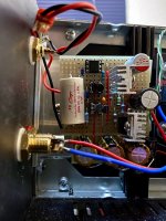
Here is what my ACPre currently looks like, implemented in veroboard. Same as dBel84 mentioned, I changed R9 to 3.0k, R12 to 3.2Ω and left R13 at 6.8Ω. I had to use two separate power feeds onto the board, shown as VDD+ and VDD. Since this board is being used as a gain stage inside a MoFo monoblock, which has 26V power to the Mosfet follower, it was necessary to drop the voltage down to 24V with an RCRCRC network. Measuring the voltage across the first R in that dropping network gives me 100 mA total being consumed by the ACPre board. The VDD+ tap point is taken after the second R, and is at 24V. The VDD tap point is taken after the third R.
The small heatsinks on the IRFP610 output devices are too hot to touch for more than two seconds, which is on the upper limit of what I find acceptable. My initial configuration of the ACPre board had even more voltage at VDD+, which made the outputs too hot to touch even briefly.
I adjusted the gain of the ACPre by changing R5 and R6 to 30.0k and R7 to 39.2k. This produces a gain that both computes and measures at 11.1 dB. I'm using 20pF for C5 because that's what I had available. I also found it much easier to get a stable current source for the input differential pair by using two J113 in parallel for Q3. I did some simple sorting to find a pair that worked with 120Ω at R4.
Attachments

Thoroughly check the opto and every component connected to it.
Are you using surface mount resistor on the opto?
Are you using surface mount resistor on the opto?
Uncertain New Guy (Wants to build an ACP+)
I finished up an ACA Amp recently. Version 1.8. It is in my office playing sweet tunes and was a fun Project. Now I want a preamp to stick between my DAC and the ACA and this seems like a good fit (my other consideration was an Objective 2 modified with some extra RCAs to work as a preamp). I just need a board, some parts, a little guidance and I can figure out a case as needed. Is my best bet to just be patient and wait until the DIYAudioStore has some of this stuff in stock (The ACA Kit I bought from them was extremely well done)? Or, is there another more interesting path I should be taking? I am a rookie at the soldering things together stuff and an old hand at the mechanical stuff and this is a new hobby for me.
Thank you kindly for any guidance you can give.
Hoping to get some direction with troubleshooting.
I replaced the opto and the source resistors . I used 1 W versions this time and managed to buy enough time to grab a few measurements
The RC filter is seeing 915mA across the 1 ohm resistors, I increased the “lower” source resistor to 10 ohm as suggested and am seeing 860mA across this resistor ( 8.6V / 10R ) .
I have double / triple checked values of resistors and all seem appropriate. Mosfets are not shorted.
The odd thing is that both units I have built behave the same which implies to me that I have made the same error on both and cannot seem to find it,
What circumstance would drive that amount of current through the mosfets, this might help me isolate what I have done wrong .
Thanks for any guidance..dB
Are the optos orientated correctly?
Do the optos you have, possibly have a different pinout configuration than standard?
Do the optos you have, possibly have a different pinout configuration than standard?
That is something I never considered but it looks correct , I used the Vishay IL217AT.

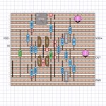
I added a few probe attachment sites for fear of shorting things out. The wire bridge is to connect pins 2 and 5 because this was an omission in the PCB layout. The upside down resistor (R9) next to the opto is the 3K resistor which i used in place of the original 1K5 ( per tungstenaudio mods to reduce bias ) [ other mods R12 is 3R2 and R13 is 10R ] rest of circuit is unchanged
I had convinced myself that replacing the OPTO would resolve the issue but it must be something else I have done, short of stripping it down and starting again, I will retest every component to make sure I have not missed anything.
dB
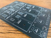
top side in case it helps

I added a few probe attachment sites for fear of shorting things out. The wire bridge is to connect pins 2 and 5 because this was an omission in the PCB layout. The upside down resistor (R9) next to the opto is the 3K resistor which i used in place of the original 1K5 ( per tungstenaudio mods to reduce bias ) [ other mods R12 is 3R2 and R13 is 10R ] rest of circuit is unchanged
I had convinced myself that replacing the OPTO would resolve the issue but it must be something else I have done, short of stripping it down and starting again, I will retest every component to make sure I have not missed anything.
dB
top side in case it helps
Last edited:
Outside of checking orientation of opto, closely inspect R11 and C4.
If both channels are having the exact same problem, it seem most likely that the opto is installed in the wrong orientation on both boards.
Or you have a short across one or both of the resistors R12/R13
If both channels are having the exact same problem, it seem most likely that the opto is installed in the wrong orientation on both boards.
Or you have a short across one or both of the resistors R12/R13
Not to worry Carsten.
Thanks for the reply.
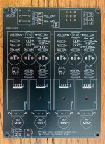
Whilst we're waiting for the official boards, I have 4x spare boards (withmatt design) from a PCB fabrication run available.
Black, £12 each, shipping to be decided based on location (100g letter).
PM me if interested.
Attachments


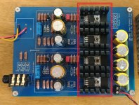
What is the solder junction across R116 on your board?
Why is R115 (or is it R114) not installed?
It would be good to have a circuit diagram that uses the component numbering on the board.
Why is R115 (or is it R114) not installed?
It would be good to have a circuit diagram that uses the component numbering on the board.
Last edited:
- Home
- Amplifiers
- Pass Labs
- Amp Camp Pre+Headphone Amp - ACP+