I have now checked R6 on left channel, and, yes, 6l6 and others were right. With the counterclockwise setting, resistance was 500 ohm and when turned fully clockwise it went don to 1.5 ohms. I will adjust the rest and turn only one channel on at a time, as suggested by 6l6 (why did I never think of that?).If I have blown any components, which one do you all think is the most likely one to go first.
Thank again
Thank again
Plans never go like you planned.
Had to help a friend replace a water heater which took most of the day.
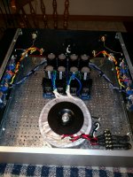
Both boards passed the light bulb test, which is good.
This what I have to dial it in, not optimal I am sure, will this be acceptable?
Thanks, Greg
Had to help a friend replace a water heater which took most of the day.
Both boards passed the light bulb test, which is good.
This what I have to dial it in, not optimal I am sure, will this be acceptable?
Thanks, Greg
Attachments
Ok, and maybe the not so good.
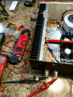
Getting 2 mV across the outputs at power up.
P1 and P2 confirmed across the associated resistors
From everything I have read, all 3 DMMs should read 0.
The output voltage also climbs after the power switch is shut off as the caps discharge.
Did I ball something up?
Getting 2 mV across the outputs at power up.
P1 and P2 confirmed across the associated resistors
From everything I have read, all 3 DMMs should read 0.
The output voltage also climbs after the power switch is shut off as the caps discharge.
Did I ball something up?
to flamethrower #408 and #410
Hello flamethrower,
2mV offset at loudspeakeroutput is nothing to worry about.
If I start up my amps I often go up to 50mV offset (at loudspeaker output)
during adjustment of POT 1 and POT 2.
I think you read the biasing procedure?
Turning POT 1 till your offset at the speakeroutput climbs to somethng between
20mV to 50mV.
Then turn POT 2 till your offset at speakeroutput comes back close to 0 mV offset. You will not get 0 mV! It is fluctuating / drifting to + or minus some mV.
That is normal. Your MOSFETS are starting to work / to be biased.
And they start to heat up - this causes a drift on your loudspeaker-offset-readings.
Turn your TRIMPOTS slow! Give the amp time to warm up (after adjustment
of POT 1 or POT 2).
Then again. POT 1 a little bit more - till your speaker output offset goes up to
circa 20-50mV. Then turn POT 2 to bring the offset (speakeroutput) back close
to 0 - 10 mV.
Check your voltage over the bias resistor of one N-channel MOSFET with one DMM..
Check your voltage over the bias resistor of one P-channel MOSFET with one
DMM.
Only adjust one channel!
This is a time consuming procedure. I often need an hour for one channel.
#410
If you switch off your amp, it is normal that your readings on the DMM at
the loudspeakeroutput are running away.
I hope this helps a little bit.
Greets
Dirk")
Hello flamethrower,
2mV offset at loudspeakeroutput is nothing to worry about.
If I start up my amps I often go up to 50mV offset (at loudspeaker output)
during adjustment of POT 1 and POT 2.
I think you read the biasing procedure?
Turning POT 1 till your offset at the speakeroutput climbs to somethng between
20mV to 50mV.
Then turn POT 2 till your offset at speakeroutput comes back close to 0 mV offset. You will not get 0 mV! It is fluctuating / drifting to + or minus some mV.
That is normal. Your MOSFETS are starting to work / to be biased.
And they start to heat up - this causes a drift on your loudspeaker-offset-readings.
Turn your TRIMPOTS slow! Give the amp time to warm up (after adjustment
of POT 1 or POT 2).
Then again. POT 1 a little bit more - till your speaker output offset goes up to
circa 20-50mV. Then turn POT 2 to bring the offset (speakeroutput) back close
to 0 - 10 mV.
Check your voltage over the bias resistor of one N-channel MOSFET with one DMM..
Check your voltage over the bias resistor of one P-channel MOSFET with one
DMM.
Only adjust one channel!
This is a time consuming procedure. I often need an hour for one channel.
#410
If you switch off your amp, it is normal that your readings on the DMM at
the loudspeakeroutput are running away.
I hope this helps a little bit.
Greets
Dirk
Thanks Dirk.
After getting firing up the first board and seeing something other than 0 at the output on one board.
I unhooked that board and hooked up the other one.
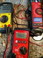
That board also read 1.3 mV, that got me thinking "how could this be".
I checked, rechecked everything as I was populating the boards.
Also, I thought at this point, I had better verify all three meters see the same thing so I can be sure to trust them.
One of the meters I had would not read mV even though it was auto ranging.
So, will have to get another meter I guess.
Will follow your suggestions when I get one.
Thanks Greg
After getting firing up the first board and seeing something other than 0 at the output on one board.
I unhooked that board and hooked up the other one.
That board also read 1.3 mV, that got me thinking "how could this be".
I checked, rechecked everything as I was populating the boards.
Also, I thought at this point, I had better verify all three meters see the same thing so I can be sure to trust them.
One of the meters I had would not read mV even though it was auto ranging.
So, will have to get another meter I guess.
Will follow your suggestions when I get one.
Thanks Greg
Attachments
On trimpot #3. I have seen mentioned, that you can leave it out if you cannot analyze the effect. If you leave it out, what do you do. Replace it with a resistor or leave the mounting holes empty or short circuit the mounting holes or what ??
Leave the mounting holes empty.
Thanks Dirk.
After getting firing up the first board and seeing something other than 0 at the output on one board.
I unhooked that board and hooked up the other one.
That board also read 1.3 mV, that got me thinking "how could this be".
...
Hi Greg,
Anything under 50mV is acceptable, although I like to see it stay in single digits (< 10mV). Keep in mind that even if you get it down to 1.3 or 2.0mV it's going to wander around a bit so it won't necessarily stay there.
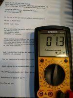
@Flamethrower - I saw a familiar set of steps on your paper...
Is this what is causing you pause from Dirk's post here?
Another F5 Build
"Switch the amp on. Be prepared to switch it off in a case of emergency.
All 3 DMMs should show 0.0 mV - if not - something is wrong.
Now you start to adjust P1 and P2:"
If so, I think even Dirk himself has advised moving on. 1.3mV is nothing to worry about. It doesn't need to be 0.0mV on all three.
Last edited:
Awesome! Can't wait 'til you get it going. I've been enjoying watching the progress.
Full trust in you, but are you really sure you need another DMM? Depending on the model, even if it's auto-ranging, it may not display really low voltages unless you manually choose the range. You may have a range button to force it to 0.000V resolution or 0000 mV resolution or similar. With mine, I actually like "roughing in" the voltages on a lower resolution setting so it doesn't look like it's drifting so much. Then once I get it really close, I can increase the resolution.
If you're willing... maybe try beginning the process of biasing / nulling offset until you start to get into the 10s or 100s of mV on one meter, then if you swap leads to your suspect meter and get nothing - you may need a new meter. Either way, I fully understand taking the most cautious approach. The thought of burning something up for me was a bit paralyzing during my first few builds.
Last edited:
Have you tried fresh batteries?
With that meter, do you get zero if you just short the leads together?
What you do want to to make sure the meter can measure a few tens of mV
offset reasonably accurately.
And if you do have a dud meter but two good ones, just use one for bias measurement
and the other on the offset.
With that meter, do you get zero if you just short the leads together?
What you do want to to make sure the meter can measure a few tens of mV
offset reasonably accurately.
And if you do have a dud meter but two good ones, just use one for bias measurement
and the other on the offset.
Last edited:
- Status
- This old topic is closed. If you want to reopen this topic, contact a moderator using the "Report Post" button.
- Home
- Amplifiers
- Pass Labs
- F5 V3