So looking into building boards again.
I see punkydawgs does not have anymore of the Toshibas available anymore.
Any body have a good verified source?
I went to
https://www.ebay.com/str/punkydawgs?_trksid=p2047675.l2563
and he seems to have plenty.
And there are batches headed to the diyAudio store.
I got back to this project today after a much needed "cooling off" period.
After evaluating the situation, I went with 6L6 instructions to change the resistors.
I was actually able to stand the amp on one side and replace them without removing the boards.
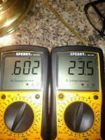
So the pic are my results after maybe 30 minutes in.
It has been cooking for an hour now and is now .606/.607 and 24/25 mV.
Is that acceptable?
And how important is it to get them exact from channel to channel.
I am new at this so, be easy on me.
Anyway, things are behaving as they should so, hopefully I got really lucky and all is good.
Thanks for your help and support
Greg
After evaluating the situation, I went with 6L6 instructions to change the resistors.
I was actually able to stand the amp on one side and replace them without removing the boards.
So the pic are my results after maybe 30 minutes in.
It has been cooking for an hour now and is now .606/.607 and 24/25 mV.
Is that acceptable?
And how important is it to get them exact from channel to channel.
I am new at this so, be easy on me.
Anyway, things are behaving as they should so, hopefully I got really lucky and all is good.
Thanks for your help and support
Greg
Attachments
Acowans,Hi folks, I"m interested in buying and then building the F5 amp, looking to see if the entire kit with boards, transistors, resistors, caps, PSU and chassis is avail at the DIYsudio store?
I think the latest version is version 3?
thanks !
You can buy the F5 boards and the associated 'F5 Parts Kit' from the store. You can buy the power supply board and chassis (4U or 5U deluxe perhaps) from the store also. You will need to source the individual components (probably from digikey or mouser) for the power supply because they don't have a prepackaged parts pack for that.
Congrats! We'll done for bringing it back from the brink. Looking forward to your thoughts on the sound too.. dB
You can not even imagine how glad I am at this point.
That stupid mistake could have gotten expensive
Fantastic news! Way to stick with it.You can not even imagine how glad I am at this point.
That stupid mistake could have gotten expensive

Flamethrower - your values are about as good as can possibly be had. There will always be a little difference between the PNP and NPN sides of the circuits, and achieving zero offset is impossible, particularly when there is a signal. As suggested, go back and see if they’ve drifted in a day or two and if not, close it up, listen to your awesome amp and don’t touch for many years. ")
Tooppy - increase value of resistors R5 R6 to 4.7k (change resistors or add resistors in series) and re-bias. You will get the full .6v drop across the source resistors. This is a very common change to get the amp to bias properly.
Tooppy - increase value of resistors R5 R6 to 4.7k (change resistors or add resistors in series) and re-bias. You will get the full .6v drop across the source resistors. This is a very common change to get the amp to bias properly.
@Flamethrower: Congratulations! Enjoy your amp.
@Toopy: That's usaully just a combination of jfet with Idss on the low side, mosfet with Vgs on the higher end. What 6L6 suggests will solve it. Remember to zero out the P1 and P2 before you power up after changing the resistsors. You can do that by adjusting P1 and P2 so that the measured resistance across R5 and R6 are low (say, no more than a few ohms)
@Toopy: That's usaully just a combination of jfet with Idss on the low side, mosfet with Vgs on the higher end. What 6L6 suggests will solve it. Remember to zero out the P1 and P2 before you power up after changing the resistsors. You can do that by adjusting P1 and P2 so that the measured resistance across R5 and R6 are low (say, no more than a few ohms)
Thanks to both of you, I am searching for the right reference in Vishay.
I found this one :
RN55D4701FB14 Vishay / Dale | Mouser France
Could it be OK ?
I found this one :
RN55D4701FB14 Vishay / Dale | Mouser France
Could it be OK ?
Can I just solder terminal blocks anywhere a wire needs a connection in every instance while I build this thing? So that it's modular and I can disconnect and reconnect wires easily? Is there a reason soldering is better than a terminal block? It looks like people have done at least that with the power supply board (quick connect tabs on the rectifier side and terminal blocks on the output side.)
Thanks! Almost ready to start stuffing..
Thanks! Almost ready to start stuffing..
- Status
- This old topic is closed. If you want to reopen this topic, contact a moderator using the "Report Post" button.
- Home
- Amplifiers
- Pass Labs
- F5 V3