Questions and observations about Wayne's 2018 linestage
Finally, after massive miss-deliveries, one of the 3 orders I have out for the 10 pF caps paid off and arrived. Now the unit is dead silent, been playing for a while with offset meandering from about .7 mV to 6 mV.
I have a question about gain...It was said somewhere in this thread around 11-12? Mine seems a little wonky in that the gain seems to climb quickly with the first half of the pot, then the second half not much happens.
I am using a 25K Chinese Ladder deal from ebay, which I have used previously in 2 of my BA3 FE projects with no oddities.
Is this typical of this unit? ( the line stage ) Need to stare at the pot's wiring a little bit, but otherwise all seems normal. The BA3 units continue to climb in volume all the way through the pot's range of travel. Here, it seems to climb quickly until about 1/2 way through the travel, then nothing more to be "gained" through the second half.
Comments?
Almost there, then I am building the second set of boards with the larger outputs. Would like to figure out this volume issue before that, if there is one. Plenty of volume, just seems odd the second half of travel does little or nothing. I suspect a miss wire, but all seems fine otherwise. Maybe it is just the way it is? Or something to do with a 25K pot?
Ideas appreciated!
Russellc
Sounds fine though, dead silent, no minor switching transients on source like BA3 had.
More stark than BA3. Apples and oranges, need to listen more with different Amps and speakers.
It is in the place of the Version 1 B1 preamp, with Aleph J, and Big Econowave with JBL Bass driver and Compression horn.
Russellc
More stark than BA3. Apples and oranges, need to listen more with different Amps and speakers.
It is in the place of the Version 1 B1 preamp, with Aleph J, and Big Econowave with JBL Bass driver and Compression horn.
Russellc
It may be the temporary source? (i dont have a signal generator, so would have use some online deal or test tone off of a CD) I was using my typical temporary source, spotify on an old Samsung smart phone. This is a system near TV that is also used to watch movies, so switching to TV on an input (this TV has low gain, many time B1 is at full volume) it seemed to increase throughout the range.
I need to move this thing over to main system for better shakedown. Off set is stable from just under 1 mV to just over 2 mV, which I feel much better about than the levels I was getting!
I may still put a 10 uF Silmic and MKC by pass on the outputs. I turned down the compression driver top end a tad, caps may add a little mellow.
Russellc
Put it in main system streaming files off my laptop using player with WASAPI output to Audioquest DAC. Problem even more pronounced. Volume control only seemed to have any effect on very lowest setting, (no sound) and first click or two. Volume had to be adjusted by slider on player screen.
Strongly suspect pot miss wired, although I THOUGHT I wired it up just like the other ones I used in my two BA3 front ends.
Take a fresh look in morning, chasing pot wiring down. If I find nothing, I will substitute different pot and try again. At least it is stone quiet and off set is stable now.
Russellc
Hi Russellc,
I think what you read was probably 11 - 12 dB gain ( 12dB ~ gain of x4)
Somewhere I got the idea the gain on this thing was 11-12 dB......Am I mistaken? If it is more like 3-4 dB that might explain things as well?
Gain is approx. 4, or 12db
Russell, great to hear how quiet this circuit is. Good luck on getting your pot issue worked out.
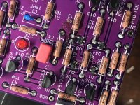
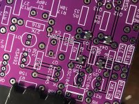
I’ve been soldering the last few days, a little at a time and wanted to post my findings on soldering iron vs hot air for the smd parts. I have a photo of each board below, the first done with my good old hakko soldering iron, and the second with solder paste and hot air from a VERY affordable Yaogong 858d unit. I have to say, the solder paste and hot air method was much easier and cleaner as you can see by the photo. I’ll be doing all of my smd work this way going forward. Excited to get the other board finished and fire them up!
I’ve been soldering the last few days, a little at a time and wanted to post my findings on soldering iron vs hot air for the smd parts. I have a photo of each board below, the first done with my good old hakko soldering iron, and the second with solder paste and hot air from a VERY affordable Yaogong 858d unit. I have to say, the solder paste and hot air method was much easier and cleaner as you can see by the photo. I’ll be doing all of my smd work this way going forward. Excited to get the other board finished and fire them up!
Attachments
I have a hot air attachment for my Weller gas iron. Would it be possible to first apply a bit of solder on each pad for the smd components and the place the component on top of that and then use the hot air to melt it down?
That would be my first try when I get these boards.
That would be my first try when I get these boards.
Pot wiring
Hello All,
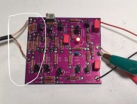
In anticipation of my boards coming in the mail (Thanks Jim!) I’ve been going over the thread, schematic in post 1, and some of the assembly pics to prepare myself for my build. I’ve noticed that the schematic doesn’t show the input pot, and the pic of the completed board below only shows + and gnd solder tabs with a two wire cable connecting the pot to the input. When wiring my pot can I simply wire it as a variable resistor with the wiper and ccw tabs shorted, or must the pot be wired as a voltage divider with the ccw tab going to ground somewhere on the board?
Thanks in advance for asking a silly question, but the B1 I built had defined connection/solder points for the cw-w-ccw tabs for the pots and I’m still a newb.
Hello All,
In anticipation of my boards coming in the mail (Thanks Jim!) I’ve been going over the thread, schematic in post 1, and some of the assembly pics to prepare myself for my build. I’ve noticed that the schematic doesn’t show the input pot, and the pic of the completed board below only shows + and gnd solder tabs with a two wire cable connecting the pot to the input. When wiring my pot can I simply wire it as a variable resistor with the wiper and ccw tabs shorted, or must the pot be wired as a voltage divider with the ccw tab going to ground somewhere on the board?
Thanks in advance for asking a silly question, but the B1 I built had defined connection/solder points for the cw-w-ccw tabs for the pots and I’m still a newb.
Attachments
Russell, great to hear how quiet this circuit is. Good luck on getting your pot issue worked out.
I’ve been soldering the last few days, a little at a time and wanted to post my findings on soldering iron vs hot air for the smd parts. I have a photo of each board below, the first done with my good old hakko soldering iron, and the second with solder paste and hot air from a VERY affordable Yaogong 858d unit. I have to say, the solder paste and hot air method was much easier and cleaner as you can see by the photo. I’ll be doing all of my smd work this way going forward. Excited to get the other board finished and fire them up!
I have never used a hot air gun such as the Yaogong, how do you keep the air from moving the part around? Tell us more about technique using it.
Hi JSA,
You need to wire the pot as a voltage divider. I can never remember the CCW/CW
nomenclature (and also I think I wired my pot upside down), but this
is roughly what I did: If you look at the three pins of the pot for each channel
then input from RCA goes to say pin 1, input ground goes to pin 3, then wire from
pin 3 goes to ground on PCB and wire from pin 2 goes to input of PCB. You may
have to switch pin 1 & 3 depending on how you're viewing the pot.
Hope that doesn't cause more confusion.")
Dennis
You need to wire the pot as a voltage divider. I can never remember the CCW/CW
nomenclature (and also I think I wired my pot upside down), but this
is roughly what I did: If you look at the three pins of the pot for each channel
then input from RCA goes to say pin 1, input ground goes to pin 3, then wire from
pin 3 goes to ground on PCB and wire from pin 2 goes to input of PCB. You may
have to switch pin 1 & 3 depending on how you're viewing the pot.
Hope that doesn't cause more confusion.
Dennis
- Home
- Amplifiers
- Pass Labs
- Wayne's BA 2018 linestage