I prefer not to connect the relay contacts in series between the amplifier and loudspeaker.
I prefer a parallel connection, which means that during normal operation when the amp is playing music, the relay contacts are not in-circuit. Just my personal preference.
Is my preference related IN ANY WAY to the failed output relay contacts on my Carver receiver, which I and many many other people had to repair? Mmmm, could be.
link 1
link 2
link 3
The idea of applying a short across the output at power on and power off could be viable.
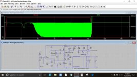
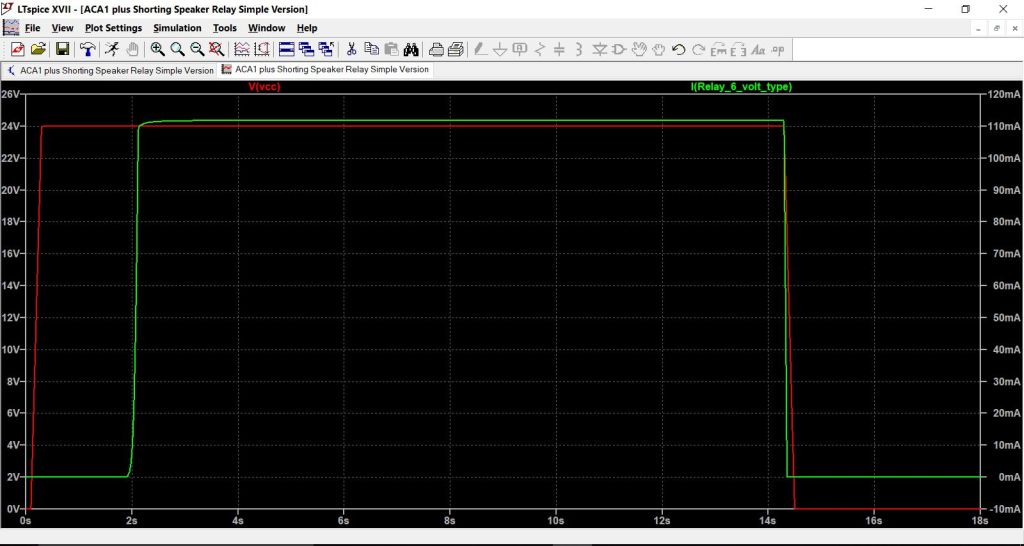
A check of the supply current of the ACA working into a shorted load is shown below. This was with an input signal that would drive the amp to clipping being applied. The peak current in this condition levels out at around 900ma per channel. So no problems as far as the PSU is concerned.
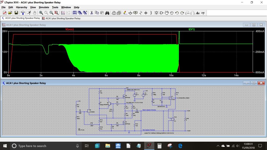
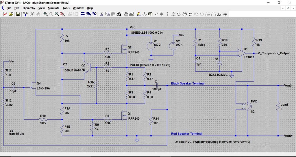
To simulate a mechanical relay I used a voltage controlled switch and set the properties at 1000meg off resistance and 0.01 ohm on resistance. Just as with the photovoltaic coupler, there is an unexpected glitch at power off. A mechanical relay that has its power removed will short the speaker as quickly as the contacts can close... which in practice should be plenty quick enough. The moment power is removed under full drive is also shown below.
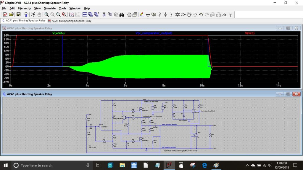
A practical version would need the comparator output interfacing to the relay via a suitable drive transistor for which I often find the 2N7000 FET (or similar) to be a useful device.
A check of the supply current of the ACA working into a shorted load is shown below. This was with an input signal that would drive the amp to clipping being applied. The peak current in this condition levels out at around 900ma per channel. So no problems as far as the PSU is concerned.
To simulate a mechanical relay I used a voltage controlled switch and set the properties at 1000meg off resistance and 0.01 ohm on resistance. Just as with the photovoltaic coupler, there is an unexpected glitch at power off. A mechanical relay that has its power removed will short the speaker as quickly as the contacts can close... which in practice should be plenty quick enough. The moment power is removed under full drive is also shown below.
A practical version would need the comparator output interfacing to the relay via a suitable drive transistor for which I often find the 2N7000 FET (or similar) to be a useful device.
Attachments


Or something with 1 or 2 555’s? Maybe using the S/R pins something can be done with 2 relays. 1 for the power and 1 for the LS. ACA powerswitch is now driving the 555 iso the power line. ACA power switch ON, first power relay, later LS relay. ACA power switch off, first LS relay, next power relay.
(The Arduino mentioned a few posts back is the easiest way, but it brings a potential noise source in the ACA box.)
(The Arduino mentioned a few posts back is the easiest way, but it brings a potential noise source in the ACA box.)
Last edited:
Can not explain
I had ugh, a long time ago(38 yrs ago), a SS Dynaco with a big turn on thump. I know this problem.
I also have built an ACA, but use a linear PS. With 91db speakers there is no turn on/off thump. However I first started with a set of CPU PSs and never had the turn on/off thump? I switch the PS ac on/off.
The only minor deviation from the "normal" components is using a MKC input cap instead of the normal silmic.
just a thought......
Hmm I have /had a Dynaco st120.. it featured that turn "thump' and a just as concerning turn off piston action on my 94 db drivers.. grrr.
Did finally fix it. Can't remember how tho😱.
Notwithstanding that it was a Genuinely Bad sounding amp.
That! remains as memorable.
Are these ACA Noises Only associated with using SMPS ?
Did finally fix it. Can't remember how tho😱.
Notwithstanding that it was a Genuinely Bad sounding amp.
That! remains as memorable.
Are these ACA Noises Only associated with using SMPS ?
Last edited:
Ops
I forgot one other change I made to the original circuit. I did raise the input impedance up to 28k to accommodate a tube preamp.
I forgot one other change I made to the original circuit. I did raise the input impedance up to 28k to accommodate a tube preamp.
...Are these ACA Noises Only associated with using SMPS ?
I would think so.
I`ve build an ACA with an ZEN like regulated PSU (Articles at Firstwatt.com)
and have not seen such Problems.
No turn on or turn off thumb.
Speakers where 91db/8ohm this time.
So try a ZEN PSU. Maybe this would help too.
Ahhh.. thank you. If that's the case.. then it's as simple as using a linear (DIY Store) PS rather than the laptop smps things ?
Seems Too easy 😉
Seems Too easy 😉
The current used by the arduino are very small. According to this site 54mA. A Solar Powered Arduino UnoAlbert, that is 'my type of hammer' also! 🙂
Wouldn't you be afraid that the 'noisy' arduino could affect the highly-sought-after clean supply?
I am not sure how much "arduino"-noise would get through the diodes used to drop the PSU voltage to arduino acceptable levels (or how much noise the diodes themselves introduce for that matter).
Radiation is another matter. If it turns out to be a problem, the arduino itself could be positioned so it does not radiate to the ACA circuitry (in a small metal box for shielding?).
The relay will use power while the ACA is in the stable phases (i.e. when you are listening). The relay can be placed anywhere, but probably close to the speaker terminals (with short leads) would be best. I have no idea if a relay pollutes the supply or radiates much noise.
If only things in the analog world were as simple as in the digital world haha
Thinking about this a bit more... for those of you using the SMPS there could actually be far simpler ways of creating a silent start up (that's probably the easy bit) and also (with a bit of thinking outside the box) a silent shutdown.
The shorting relay across the output has to be silent at power on. It can't be anything else. That means a simple single transistor such as a 2N7000 FET powering the relay, and with a simple R/C delay on the gate would work. That is your silent switch on.
The relay closing when the ACA is switched off has to be accomplished very quickly. One possible approach could be to use a low voltage relay (5 volt) with appropriate Zener in series with the coil. As soon as the supply falls a little the relay will drop out shorting the speaker.
The above would be a unique (bit reliable) one off solution to the ACA using its recommended SMPS given that the SMPS output is both very tightly defined and that it will fall very quickly once the mains input is removed.
Don't forget the 'normal' power system for the ACA is;
smps -> chassis connector -> SWITCH (in the positive) -> ACA modules.
This means you will have both a permanent, and a switched 24v supply available inside the ACA chassis.
Therefore, a relay with a 24v coil, powered from the switch, should power down the instant the power switch is turned off.
Only leaving some sort of delay to be implemented for turn on delay.
Last edited:
Don't forget the 'normal' power system for the ACA is;
smps -> chassis connector -> SWITCH (in the positive) -> ACA modules.
This means you will have both a permanent, and a switched 24v supply available inside the ACA chassis.
Therefore, a relay with a 24v coil, powered from the switch, should power down the instant the power switch is turned off.
Only leaving some sort of delay to be implemented for turn on delay.
Thanks, I hadn't realised that.
You would want it silent under all possible user conditions though 🙂
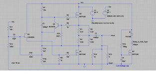
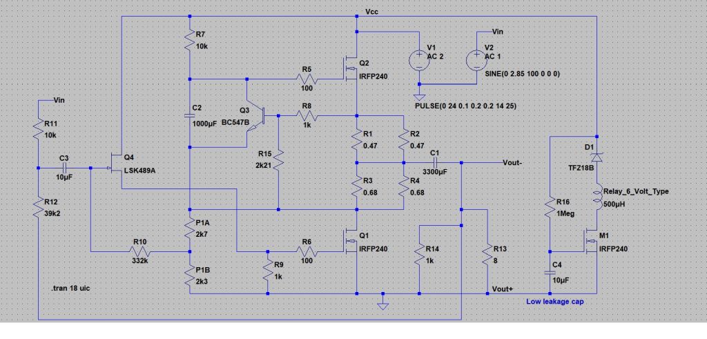
I looked at this a little more and this could be a winner... a simple circuit based on what I outlined above.
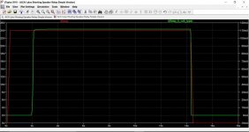
Here we can see the current in the relay coil vs supply voltage. Delay can be anything you want although bear in mind cap leakage currents vs current available to charge the cap. In other words a 10meg and 10uF electrolytic might not work as expected. Also a diode in inverse parallel (not shown across the timing resistor) would enable the circuit to be ready for action immediately following a switch off event. An inverse diode across relay is probably not necessary due to relatively slow transition times and the fact the FET already has an inverse diode 'built in', an unavoidable (but sometimes useful) function of the manufacturing process.
Attachments
I was thinking precisely that! The main is never 'removed'. You always have the SMPS on and connected. It's just interrupted via switch.
Perhaps that could be taken advantage of.
Ps. Mooly's reply came through as I was writing.thisis I reply to Oldn'Cranky
Perhaps that could be taken advantage of.
Ps. Mooly's reply came through as I was writing.thisis I reply to Oldn'Cranky
... An inverse diode across relay [coil] is probably not necessary due to relatively slow transition times and the fact the FET already has an inverse diode 'built in', an unavoidable (but sometimes useful) function of the manufacturing process.
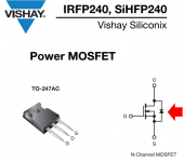
Erm, not quite. The N-channel MOSFET has a large and robust drain-to-bulk diode, whose cathode (N doped silicon) is connected to the drain and whose anode (P doped silicon) is connected to the bulk and to the source pin. Unfortunately this diode clamps in the wrong (unneeded) direction. It clamps negative excursions on the drain, quite thoroughly.... but what we need is a way to clamp the positive excursion on the drain from the flyback event, when the MOSFET turns off and the voltage across the inductor jumps to (L * dI/dt) which is an enormous positive voltage. Since the IRFP240 is guaranteed to survive 200V on its drain, a simple <<200V zener diode from drain to source (i.e. ground) will do the trick. To name one example, Mouser has lots of 36V zeners in stock and LTSPICE has several 36V zeners in its presupplied device-model library.
Textbooks connect a normal PN diode across the relay coil but that's old hat and boring. Let's have some fun with an alternate topology that has the same parts count and the same parts cost, but a new and exciting schematic.
_
Attachments
Last edited:
^ True. Thanks Mark 🙂
I was hazily thinking the diode would protect the drive transistor from inverse polarity (which it will). Any positive excursion would be dumped via the Zener into the supply rail.
The speeds the drive transistor switches at are so slow that I doubt there would be any measurable transients tbh.
I was hazily thinking the diode would protect the drive transistor from inverse polarity (which it will). Any positive excursion would be dumped via the Zener into the supply rail.
The speeds the drive transistor switches at are so slow that I doubt there would be any measurable transients tbh.
Thanks, I hadn't realised that.
You would want it silent under all possible user conditions though 🙂
I looked at this a little more and this could be a winner... a simple circuit based on what I outlined above.
Here we can see the current in the relay coil vs supply voltage. Delay can be anything you want although bear in mind cap leakage currents vs current available to charge the cap. In other words a 10meg and 10uF electrolytic might not work as expected. Also a diode in inverse parallel (not shown across the timing resistor) would enable the circuit to be ready for action immediately following a switch off event. An inverse diode across relay is probably not necessary due to relatively slow transition times and the fact the FET already has an inverse diode 'built in', an unavoidable (but sometimes useful) function of the manufacturing process.
This circuit won't have instant turn off in real life. Power supply capacitors won't discarge instantly...
Ok it might not disconnect within microseconds.
But even if the relay drops out within say 0.1 of a second that would be ok with me.
If this helps at all.
My observations of my ACA using the power switch that cuts power from the smps to the amp modules.
Speakers are small bookshelf 8 ohm, 4" two ways, Unknown sensitivity but I'd estimate mid 80's.
Turn on.
At the one second mark the bass driver sucks in a little,
half a second later you hear the 'farting' noise for two seconds,
followed by small cone movements.
In total the bass driver has some sort of movement for ~5 seconds.
Turn off.
At the instant of power down the bass driver 'pops' foward briefly.
Edit, as I see the schematic, there's not really that much in the way of power supply capacitance on the ACA.
Maybe, just a thinking out loud here, installing a moderate size cap on the modules ps rail will help the amp shut down slower giving more time for any relay etc to be more effective ?
Last edited:
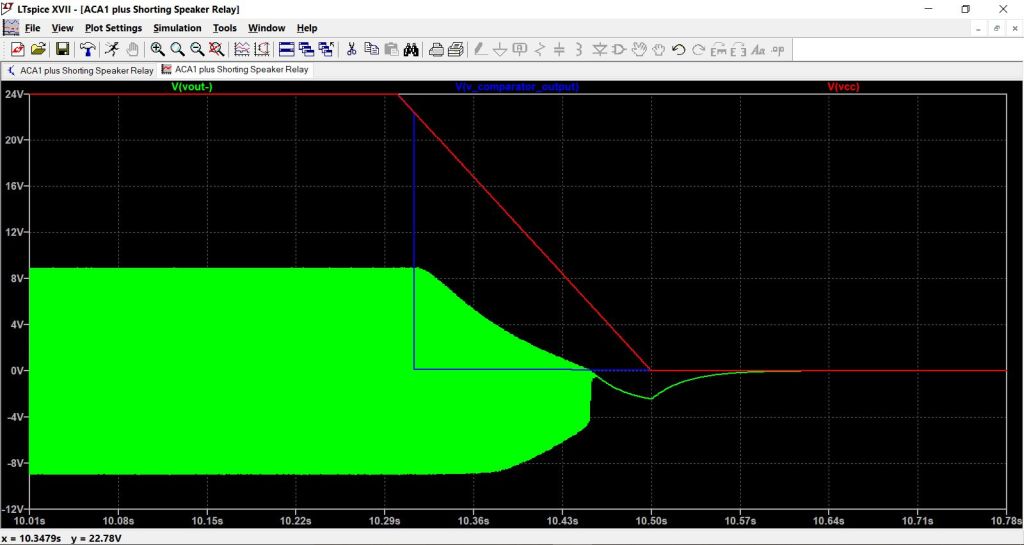
The trick is to mute the output while the (gradually falling) power supply voltage is still high enough for the amplifier to operate approximately correctly as an amplifier, and not operate as a dump a thump bumpster box. Judging from the 2nd-to-last figure attached to post #22, it appears you'd be completely safe if you let the supply voltage sag from 24V to 16V before activating the muting relay.
I just had a wild thought.
Possibly not doable with the aca, but anyway..
Instead of trying to cut or short the aca output at turn on/off.
Why not something like the retail pass labs amps where the front panel switch drops the bias to ?? whatever it is.
A standby switch as it were.
Possibly not doable with the aca, but anyway..
Instead of trying to cut or short the aca output at turn on/off.
Why not something like the retail pass labs amps where the front panel switch drops the bias to ?? whatever it is.
A standby switch as it were.
This circuit won't have instant turn off in real life. Power supply capacitors won't discarge instantly...
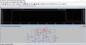
Indeed they won't. I set the fall time of the simulation to just 0.2 seconds which seemed a fair guess for a 'brick' type SMPS delivering 3amps. The fall time may even be quicker than that.
This shows an extra 20,000uF capacitance added to the rail (together with a diode to prevent the voltage source interfering with the discharge time).
There is no issue. Remember the reservoir caps in the SMPS will be very small indeed compared to the values we would use with a linear supply.
Attachments
- Status
- Not open for further replies.
- Home
- Amplifiers
- Pass Labs
- A possible approach to adding a silent start/shutdown to the ACA