I just had a wild thought.
Possibly not doable with the aca, but anyway..
Instead of trying to cut or short the aca output at turn on/off.
Why not something like the retail pass labs amps where the front panel switch drops the bias to ?? whatever it is.
A standby switch as it were.
Its a good idea for those that like to leave things powered up but it could be difficult to implement.
Although reducing the bias current to near zero is easy, the problem with the ACA is that doing this also changes the DC conditions and so the speaker cap will be 'resting' at a different voltage. When correct bias is restored the change in voltage will cause some kind of noise... maybe not as bad but it won't be silent.
The simulation shows quite well the voltage pulses you mention and even the cone settling (a small damped very low frequency settling) but not the weird noise that many have mentioned (there is a recording of this that I have heard). I have wondered if that noise is the SMPS initially starting up under almost full load conditions and consequently the rail not being clean during that time. That's easy to check for real with a scope with a scope across the rail at start up.
Here is the speaker current at switch on and switch off.
Attachments

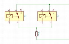
Assume we use the power resistor parallel to the speaker output. Instead of using 1 relay to switch it into the circuit, we use 2, one with R/C delay circuit and one without.
The relay WITH R/C delay circuit takes care of power on instability.
The relay WITHOUT R/C delay circuit takes care of power off instability.
As long as either is closed during any unstable phase, we have shunted the unstable output.
Required:
1 x Power resistor to use as shunt
1 x Relay with R/C delay circuit that only closes a few seconds after power is available
1 x Relay (without R/C delay circuit) that will close as soon as V < say 20V.
At power on: The relay with R/C delay circuit stays open for a few seconds, so there is an alternative path during the unstable phase and hence no thump.
Note: It does not matter that the other relay closes as soon as there is power.
At power off: The relay without R/C delay circuit opens before instability occurs, so there is an alternative path during the unstable phase and again no thump.
Note: It does not matter that the relay with R/C delay circuit stays open for a few seconds.
You can use 24V relays, as long as the relay without R/C delay closes soon enough (check datasheet). Alternatively, drop voltage using (zener) diodes(s) and use with an appropriate voltage relay.
Attachments
Last edited:
There are many possibilities but I would question using two relays when one should be able to do the job.
Also remember that a typical relay when supplied with its nominal coil voltage (say 24 volts) would remain operative down to perhaps as low as 5 volts. That would be fairly typical behaviour for a standard relay.
Also remember that a typical relay when supplied with its nominal coil voltage (say 24 volts) would remain operative down to perhaps as low as 5 volts. That would be fairly typical behaviour for a standard relay.
The simulation shows quite well the voltage pulses you mention and even the cone settling (a small damped very low frequency settling) but not the weird noise that many have mentioned (there is a recording of this that I have heard). I have wondered if that noise is the SMPS initially starting up under almost full load conditions and consequently the rail not being clean during that time.
Gasp ! possibly suggesting that the thrice cloned 9$ Ebay 'Laptop' SMPS isn't as clean as it could be ?? Please say it ain't so.
I've now seen two references to linear supplies resulting in silent startup / shutdown.
Amp Camp Amp - ACA
And with the posts in this thread that the noises maybe from the smps (ringing ?) on startup.
This makes me wonder about an intermediate power supply section for those running the standard aca with smps.
Something along the lines of a capacitor bank or crc stage that goes between aca and the switchmode.
I wonder if the simulation software can emulate what happens in those situations ?
Noise on rails can be simulated, as can the effectiveness of any rail filtering.
A non SMPS type supply is going to have pretty quick rise and fall times, even with huge capacitor banks and the ACA will still have the same settling time as the SMPS version.
Although you can reduce switch on noise by various tricks and techniques, the large 3300uF speaker coupling cap has to charge and discharge via the speaker and that means that noise of some kind (or cone movement) is inevitable.
Agreed. Conceptually, it is easier to understand using 2 relays. It can be done with 1:There are many possibilities but I would question using two relays when one should be able to do the job.
Feed the output of:
--- the R/C or "have 3 seconds elapsed since start-up?" circuit
and
--- the zener or "is the voltage > 22V?") circuit
to a logic AND. Use the output of the AND gate to switch the (one and only) relay. The AND gate ensures it will only close when both conditions have been met and remove the shunt resistor from the circuit.
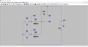
I have never built an AND gate (my experience is software, not hardware), but I understand you only need 2 diodes and a resistor to do the trick.
This is easily fixed by using a 5V relay and an appropriate zener to drop PSU voltage from 24V to 5V. I assume the relay will open when voltage is 1V (PSU still at 20V), but it certainly should 0V (PSU is still at 19V). This should be soon enough as instability is at 15V (see you simulation in early post). The only thing I am not sure of is how long the realy will take to open, but that problem is the same for any solution using a relay.Also remember that a typical relay when supplied with its nominal coil voltage (say 24 volts) would remain operative down to perhaps as low as 5 volts. That would be fairly typical behaviour for a standard relay.
Attachments
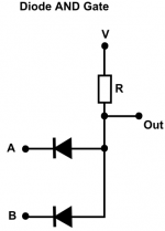
Your diode AND gate would give an output equal to the voltage on either A or B. Whichever was the lowest voltage would appear at the output (plus the forward voltage of the diode).
The way I understand it, A and B are tied to ground with a suitable resistor.
Voltage will presents as follows:
If A is LOW and B is HIGH it will go to A.
If B is LOW and A is HIGH it will go fo B.
If A and B are LOW it will go to both.
Only when A and B are HIGH (effectively blocking the path) will it go to OUT.
Voltage will presents as follows:
If A is LOW and B is HIGH it will go to A.
If B is LOW and A is HIGH it will go fo B.
If A and B are LOW it will go to both.
Only when A and B are HIGH (effectively blocking the path) will it go to OUT.
Last edited:
To be clear on how (you) intend it to work means that you need to define levels.
A and B can only pull the voltage on 'Out' down. 'Out' would normally equal the supply voltage and that presumably would be your definition of 'High'.
If V were 100 volts then leaving A and B floating, or connecting one or the other in any combination to 'V' would leave the output unchanged.
Connecting A or B in any combination to ground or to some other voltage would pull the 'Out' voltage lower. By how much depends on the voltage at terminals A and B. The terminal at the lowest voltage would be the one in control of the final output voltage.
Disregarding the diode drop we have the following when on a 100 volt supply. O = 'Out':
A=0
B=0
O=0
A=100
B=100
O=100
A=0
B=100
O=0
A=100
B=0
O=0
A=20
B=100
O=20
A=75
B=73
O=73
Any resistors added would simply form a divider with your load resistor. Again the terminal at the lowest voltage would be the only one active and influencing the result.
I thought that the way the diodes are pointing, a voltage from A and/or B cannot reach OUT.
I thought that a voltage applied at V can go to A, B or OUT.
Let's assume 5V at V, 5V = HIGH and 0V = LOW.
V, A and B are at 5V. OUT is at 5V.
V is at 5V. A or B is LOW. What is the voltage at OUT? Can the resistance of R, the (resistance of the) paths through A or B and the input resistance at OUT be chosen such that the voltage seen at OUT is LOW?
I thought that the way the diodes are pointing, a voltage from A and/or B cannot reach OUT.
Correct (assuming the voltages are all positive).
Let's assume 5V at V, 5V = HIGH and 0V = LOW.
V, A and B are at 5V. OUT is at 5V.
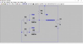
Correct. Also the output will be at 5 volts if either or both inputs float.
V is at 5V. A or B is LOW. What is the voltage at OUT?
It is equal to the forward volt drop of the diode, so around 650mv.
Can the resistance of R, the (resistance of the) paths through A or B and the input resistance at OUT be chosen such that the voltage seen at OUT is LOW?
Resistance R has no effect on the output level in practical terms. The lower it is then the more current flows in a logic 0 output condition. The lower the forward volt drop of the diode, the lower the output voltage will be. A germanium diode would be in the 150 millivolt region.
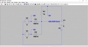
I can see you are not convinced 😉 The last image with 75 volts applied to the inputs shows a microscopic increase in output voltage due to the leakage of the diodes. This is a working simulation showing the expected voltages.
Attachments

Sorry, it's late and I will look at this more closely tomorrow. After a quick glance though, doesn't schematics 1 2 and 3 show it working as an AND gate?
If A is only 5V when 3 seconds have passed
and B is only 5V when PSU V > 20V
the output will switch the relay on, taking the shunt resistor out of the circuit.
Assuming the aprox. 700mV shown will not cause the relay to close.
If A is only 5V when 3 seconds have passed
and B is only 5V when PSU V > 20V
the output will switch the relay on, taking the shunt resistor out of the circuit.
Assuming the aprox. 700mV shown will not cause the relay to close.
Yes, it is an AND gate. Both A and B must be high in order for the output to be high.
One possible point of confusion is when you start thinking about what happens with input voltages that do not conform to assumed logic levels. In that case it is simply an analogue network with a known characteristic.
Then the output will be at around 4.35 volts.
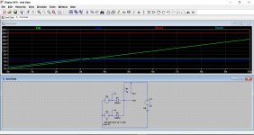
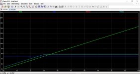
This shows a rising input voltage being applied to A. Notice how the output voltage is A + the diode volt drop. B is fixed at 5 volt.
Once A crosses the 5 volt threshold of B then it has no more effect on the output voltage. B is now in control (as it is the lower of the two voltages) and determines the output voltage.
The last image is exactly the same but now also shows the diode currents (right hand scale). You can see the point the diodes 'switch', these points corresponding to one diode becoming cut off as the other conducts at the 5 volt level.
One possible point of confusion is when you start thinking about what happens with input voltages that do not conform to assumed logic levels. In that case it is simply an analogue network with a known characteristic.
If A is only 5V when 3 seconds have passed
and B is only 5V when PSU V > 20V
Then the output will be at around 4.35 volts.
This shows a rising input voltage being applied to A. Notice how the output voltage is A + the diode volt drop. B is fixed at 5 volt.
Once A crosses the 5 volt threshold of B then it has no more effect on the output voltage. B is now in control (as it is the lower of the two voltages) and determines the output voltage.
The last image is exactly the same but now also shows the diode currents (right hand scale). You can see the point the diodes 'switch', these points corresponding to one diode becoming cut off as the other conducts at the 5 volt level.
Attachments

I see what you mean. Perhaps worth describing why I thought of using the diode AND circuit.
First of all, the digital world is a lot more compartimentalised. Something is either TRUE or FALSE, and there are no interactions (only consequences). In the analog world, pfff, anything and everything you do has an effect. From a software perspective it is very messy haha.
In my first attempt to solve the problem, I used an arduino to create a delay (re power on instability) and check voltage (re power offinstability) and effectively used a software AND to switch a relay.(Note, I had the delay before I did anything else, so the voltage would only be checked after the delay; effectively an AND).
I understand the arduino's delay function can be replaced by an R/C circuit to provide the delay. Great! That's one problem solved.
The arduino's voltage sensing can be replaced by an analog circuit (no idea what it looks like, but conceptually great!).
This just left the logical AND that was performed by the software. An easy fix was 2 relays.
When you said you would prefer 1 relay, I thought it might be possible to implement the AND in hardware, effectively translating my (compartimentalised) software approach to hardware. And that's where it got difficult because I had no idea how the analog circuit (that perform delay and voltage check) work, let alone how anything would interact. In software/logic terms it is easy!
I have had a look at the circuit and have attempted to solve the problem. Forget about the choice (and number of!) parts. It is the idea that counts.
I arbitrarily decided to concentrate on 5V logic. My shunt switch works at 4.8V.
I used a shortcut (LT1085-5) to get 5V (I did not have a 7805 model and did not want to spend time on how else this could be achieved). It's input is taken from Vcc after being passed through a 16V zener. This gets rid of the turnoff thump, because the LT1085-5 output drops before Vcc = 15V (instability occured at Vcc = 15V).
The start up delay is messy but it seems to work.
All in all it was a good way to get back into LTSpice. I know that as far as the analog world goes, I have a lot to learn!
Attachments
PS Just now, I realised that it makes sense to move the RC between Vcc and the zener to the LT1086-5. That gets rid of a lot of stufc that is no longer required.
Seems to me that if you're going to allow yourself to use integrated circuits, the low cost LM393 might be an excellent choice. You can set its trip voltage threshold very precisely, and it has extremely high impedance inputs so you can connect it to long-time-delay RC circuits without disturbing the exponential timing waveform. Since its VCCmax is 36 volts, it'll run off a 24V supply without difficulty.
- Status
- Not open for further replies.
- Home
- Amplifiers
- Pass Labs
- A possible approach to adding a silent start/shutdown to the ACA